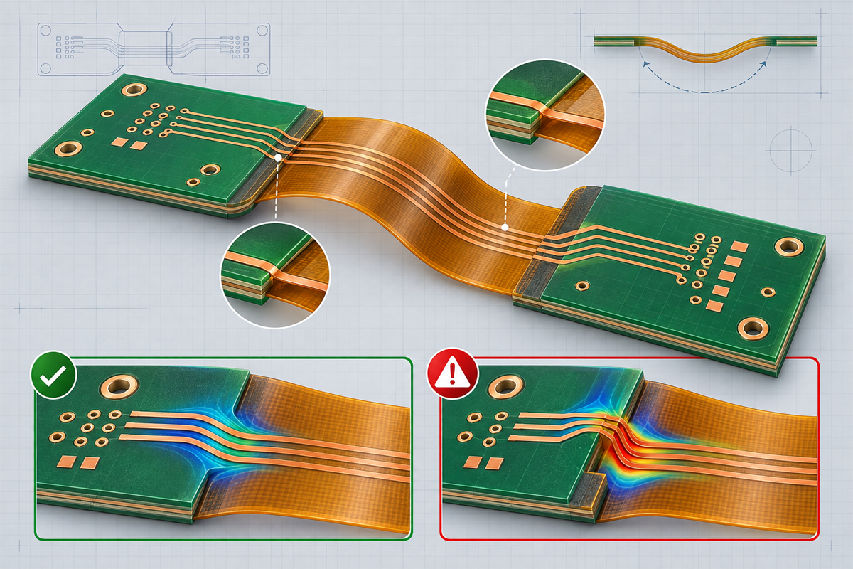
Rigid-flex transition zones are not single mathematical lines where a PCB suddenly becomes mechanically flexible. Near every rigid-to-flex boundary, the stack-up, copper distribution, coverlay, adhesive system, and enclosure support create a transition in stiffness. That region can become a high-risk location when a bend starts too close to the rigid edge, when a via or pad sits in the moving region, or when copper geometry changes abruptly as it crosses the boundary.
The practical objective is not to copy one clearance number into every design. It is to define where motion is allowed, keep concentrated features away from that region, route copper so strain is distributed, and validate the finished construction in the intended assembly. IPC-2223F is the current sectional design standard for flexible and rigid-flexible printed boards, while IPC-6013F covers qualification and performance requirements. The project drawing still has to translate those standards into construction-specific requirements.
Why rigid-flex transition zones need their own design review
A rigid section resists curvature; a flex section is intended to accommodate it. Where the two meet, bending stiffness changes rapidly. If the enclosure forces curvature to begin at that edge, the copper and dielectric system may experience a localized strain peak instead of a broad, controlled bend. A notch, a sharp inside corner, a coverlay edge, a stiffener edge, or a concentrated copper feature can intensify the effect.
This is why “the bend radius is acceptable” is not enough. Radius describes the formed geometry, but it does not by itself confirm where the bend begins, how the tail is constrained, or whether assembly tolerances can move the actual bend toward the transition. The mechanical model should include the installed shape, insertion path, housing contact, clamp or adhesive locations, and any service movement.
Separate the bend keepout from the fabrication boundary
The rigid outline, coverlay opening, rigid material relief, and intended bend line are different features. Combining them into one line on a drawing leaves too much interpretation. A useful mechanical layer should show the rigid area, flex area, transition boundaries, permitted bend zone, prohibited bend zone, bend direction, installed angle, and any dynamic or flex-to-install duty.
The bend keepout is the area where the product design must prevent curvature. It normally includes the immediate transition and may extend to protect pads, holes, component terminations, exposed copper, stiffener edges, or other discontinuities. Its final extent depends on layer count, copper thickness and type, dielectric and adhesive construction, plating, coverlay, surface finish, bending duty, temperature, and the way the assembly is restrained.
Manufacturer design rules can inform the first layout, but they must stay attached to the construction for which they were published. For example, Würth Elektronik’s Flex Solutions design guide publishes transition guidance for specific RIGID.flex variants. Those figures are useful evidence for early DFM discussion, not general IPC minimums and not automatic proof that another supplier’s stack-up is equivalent.
Copper risks near an abrupt stiffness change
Keep pads, vias, and plated features out of the moving region
Pads and vias add copper mass and create geometry changes. Plated through-holes also connect layers through the thickness of the rigid structure. Placing these features where the flex must curve can create a local stiffness jump and a stress concentration. The safer default is to keep them in the rigid area and route continuous conductors through the permitted bend zone. If a feature must be close to the boundary, it needs an explicit supplier review based on the actual stack-up and registration capability.
Cross the transition cleanly
Würth’s Flex Solutions guide recommends routing conductors at right angles to the rigid-flex transition and avoiding width or direction changes in the bending area. Molex similarly recommends routing conductors perpendicular to the bend when possible, using soft curves instead of sharp corners, and adding fillets at conductor-to-pad interfaces. The shared engineering principle is to avoid a concentrated change in direction, width, or support where mechanical loading is already changing.
Teardrops and fillets can smooth the conductor-to-pad interface, but they do not rescue a pad placed inside an uncontrolled bend. They are local geometry tools, not substitutes for a correctly defined keepout.
Avoid stacked copper “I-beams”
When conductors on opposite sides of a two-layer flex are directly aligned, the combined structure can resist bending more than staggered conductors. Both Würth and Molex identify this stacked arrangement as an I-beam concern. Staggering traces and keeping conductor distribution reasonably balanced can reduce abrupt stiffness differences. The final pattern must still respect electrical requirements, including return paths, impedance, current, and electromagnetic compatibility.
Solid reference planes also affect flexibility. Cross-hatching or planned openings can make a region more compliant, but they change current return geometry and impedance. Do not introduce hatching as a purely mechanical correction after signal-integrity work is complete. Treat copper pattern, dielectric thickness, trace geometry, and reference structure as one controlled stack-up. Our related guide on FPC impedance during bending explains why geometry and validation need to be considered together.
Stiffeners and strain relief: move the load, do not hide it
A stiffener can protect a connector, component area, or termination, but its edge creates another stiffness transition. Ending a stiffener at the same location as the main rigid-to-flex boundary can stack two discontinuities. Where possible, review whether the edges should be offset and whether adhesive fillets, encapsulant, or mechanical support are appropriate. Molex notes that strain-relief material along a hardboard edge can reduce conductor-break risk at a flex-to-rigid interface; the selected material and process still require compatibility review.
The enclosure should not pinch the flex at the boundary or force a sharp crease during installation. A service loop or additional free length can distribute movement over a larger area, but it also affects packaging, vibration, and assembly sequence. Define who forms the circuit, when it is formed, whether it is re-opened for service, and how its final shape is retained.
Decision table for transition-zone review
| Review item | Question to answer | Evidence to release | Typical risk if unclear |
|---|---|---|---|
| Use condition | Flex-to-install, service flex, or repeated dynamic movement? | Duty description, bend direction, cycle or service requirement where applicable | A static construction is assumed for a moving application |
| Installed geometry | Where can curvature begin at tolerance extremes? | 2D keepout plus 3D installed view and restraint locations | The housing moves the bend into the rigid edge |
| Stack-up | Which layers continue through the flex, and which copper and dielectric materials are used? | Controlled stack-up with supplier-confirmed materials and thicknesses | Mechanical assumptions do not match the fabricated board |
| Copper routing | Are pads, vias, neck-downs, corners, or stacked traces near the bend? | Layer-by-layer transition review | Localized strain and conductor cracking risk |
| Stiffness features | Where do coverlay, stiffeners, adhesive, shielding, or encapsulation end? | Dimensioned material boundaries | Multiple stiffness changes coincide |
| Validation | What proves the built assembly survives installation and service? | Agreed sample build, inspection, continuity, and application-specific mechanical test plan | A flat-board check misses installed mechanical stress |
A practical release workflow
- Classify the motion. State whether the flex is formed once, moved during servicing, or cycled in operation. Do not use “dynamic” without a defined motion and environment.
- Freeze the mechanical interfaces. Identify clamps, connector bodies, fasteners, housing walls, adhesive zones, and tolerance stack-ups that can control the bend.
- Draw separate zones. Mark rigid material, transition boundaries, bend keepout, permitted bend region, and any component or via keepouts on a controlled mechanical layer.
- Review every copper layer. Look for pads, vias, acute corners, sudden width changes, aligned traces, solid planes, and asymmetric copper near the transition.
- Align documentation. Make the fabrication drawing, stack-up, Gerber or ODB++ data, 3D model, and assembly instructions agree. The assembly drawing review checklist covers polarity, rotation, fiducials, and DNP control for the broader release package.
- Ask for construction-specific DFM. Confirm transition clearances, layer termination, coverlay, stiffener, material, plating, and forming assumptions with the selected fabrication source.
- Validate the assembly, not only the flat board. Inspect the formed unit and define electrical continuity or functional checks before and after the relevant mechanical exposure.
For assembly planning beyond the transition itself, see the rigid-flex PCB assembly guide. It covers handling, support, forming sequence, and test gates that should remain linked to the mechanical drawing.
Engineering conclusion
For rigid-flex transition zones, the most important control is not a single dimension. It is agreement between the installed geometry, the actual stack-up, the copper layout, and the permitted motion. Keep the first bend away from abrupt stiffness changes, keep concentrated copper features out of the moving region, route conductors smoothly, and validate the constructed assembly under a representative mechanical condition.