PCB assembly and PCBA services support electronic products that require component sourcing, SMT placement, through-hole assembly, soldering, inspection, testing, and production documentation review. A complete PCBA project must coordinate the bare PCB, BOM, component packages, assembly drawings, process requirements, test criteria, and final delivery format.
FPCFAB supports PCB assembly projects for prototypes, engineering validation, new product introduction, pilot runs, and small-to-medium-volume production. Our team can review your Gerber files, BOM, centroid data, assembly drawings, component specifications, testing requirements, and delivery expectations before quotation and production preparation.
PCB Assembly and PCBA Support
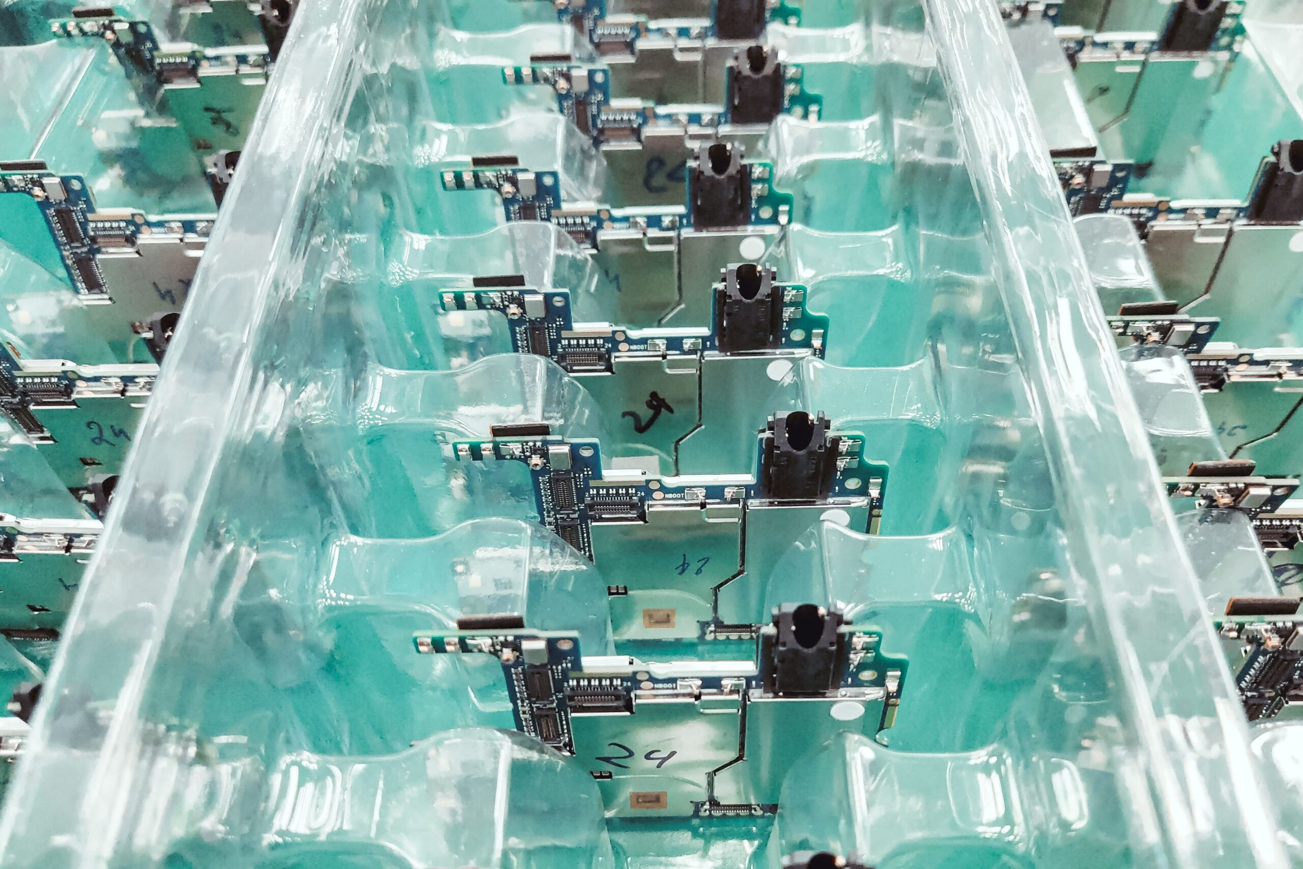
PCB assembly converts a fabricated printed circuit board into a functional electronic assembly by mounting and soldering components according to the approved design data. Depending on the project, the assembly may include surface-mount components, through-hole components, connectors, mechanical parts, cables, displays, sensors, modules, and programmed devices.
Project evaluation may cover:
- Prototype PCB assembly and engineering samples
- New product introduction and pilot-run assembly
- Small-batch and medium-volume PCBA production
- Single-sided and double-sided component placement
- Mixed SMT and through-hole assembly
- Rigid PCB, flexible PCB, and rigid-flex PCB assembly
- Connector, cable, module, and mechanical-part integration
- Consigned, turnkey, or mixed component-sourcing models
- Functional testing, programming, and final inspection requirements
Each quotation is evaluated according to board complexity, component count, package type, minimum pitch, assembly side, soldering process, inspection requirements, test scope, component availability, production quantity, and target lead time.
SMT Assembly Capabilities
Surface-mount technology is used for electronic assemblies that require compact component placement, automated production, and consistent solder-joint formation. Assembly feasibility depends on PCB pad design, solder mask definition, stencil design, component packaging, placement density, thermal balance, and reflow-process requirements.
SMT project support may include:
- Single-sided and double-sided SMT placement
- Fine-pitch integrated circuits and dense component layouts
- QFN, QFP, BGA, LGA, SOT, SOIC, and standard passive packages
- Small passive components subject to project review
- Solder paste printing and stencil review
- Automated component placement
- Lead-free reflow soldering
- Manual placement or rework for special components
- Bottom-terminated component and thermal-pad considerations
For fine-pitch, BGA, QFN, or high-density designs, the pad geometry, solder paste apertures, via structure, component clearance, thermal design, and inspection method should be confirmed before production.
Through-Hole and Mixed Assembly
Through-hole assembly is commonly required for connectors, terminals, relays, transformers, switches, power components, mechanical-support parts, and components exposed to higher mechanical loads. Many electronic products use a mixed process that combines SMT placement with through-hole insertion and soldering.
Assembly planning may include:
- Manual or process-controlled component insertion
- Wave, selective, or manual soldering evaluation
- Connector alignment and mechanical-position control
- Lead forming, trimming, and component-height requirements
- Heavy or mechanically stressed component support
- Mixed-technology assembly sequencing
- Hand-soldering requirements for special components
- Post-solder cleaning and visual inspection requirements
BOM Review and Component Sourcing
A clear and complete bill of materials is essential for accurate PCBA quotation and production planning. Missing manufacturer part numbers, unclear package information, obsolete components, allocation risk, or inconsistent reference designators can delay sourcing and increase the risk of incorrect component selection.
Our BOM review may include:
- Manufacturer part number and package verification
- Reference-designator consistency check
- Quantity-per-board and assembly-side review
- Lifecycle, availability, and lead-time risk identification
- Obsolete or difficult-to-source component review
- Customer-approved alternate-part evaluation
- Consigned-component receiving and quantity confirmation
- Moisture-sensitive device handling requirements
- Programming or special preparation requirements
Alternative components are not substituted without customer approval when the manufacturer part number, electrical specification, package, tolerance, temperature rating, or other critical requirement may affect product performance.
PCB Assembly DFM and NPI Review
Assembly DFM review identifies practical production risks before stencil preparation, component purchasing, and line setup. It is especially important for new designs, incomplete documentation, fine-pitch components, unusual connectors, dense layouts, and products requiring special test or mechanical integration.
Pre-production review may cover:
- Gerber, drill, and board-outline consistency
- BOM and reference-designator consistency
- Centroid or pick-and-place data accuracy
- Component orientation and polarity markings
- Assembly drawing and special-process notes
- Pad, solder mask, and stencil-aperture considerations
- Component-to-component and component-to-edge clearances
- Panelization, tooling rails, fiducials, and support points
- Reflow, wave, selective, or manual soldering requirements
- Test-point accessibility and fixture considerations
- Mechanical, enclosure, connector, and cable interference
- Packaging and final-delivery requirements
DFM feedback is intended to identify assembly risks before material purchasing and production setup. Final approval remains based on the customer’s design requirements and authorized manufacturing files.
Inspection, Testing, and Programming
Inspection and testing requirements should be defined according to the product application, board complexity, expected reliability, and available test documentation. Visual inspection alone may not confirm every hidden solder joint, electrical function, programmed-device condition, or system-level performance requirement.
Depending on the project scope, quality control may include:
- Incoming PCB and component inspection
- Solder paste and placement-process monitoring
- Automated optical inspection where applicable
- Visual solder-joint and polarity inspection
- X-ray inspection for BGA, QFN, or hidden solder joints when specified
- Continuity, short-circuit, or basic electrical checks
- In-circuit or functional testing when fixtures and procedures are provided
- Firmware or programmable-device loading when files and instructions are available
- First-article inspection and production sample approval
- Final cleaning, labeling, packaging, and quantity verification
Customers should provide test procedures, expected measurements, firmware files, programming instructions, fixtures, cables, reference samples, or functional acceptance criteria whenever these are required for final product verification.
Prototype and Production Assembly
Prototype PCBA projects are used to verify electrical performance, component selection, mechanical fit, firmware, testing, and assembly feasibility before larger production quantities. Early-stage builds may require additional engineering communication because design files, BOMs, or test procedures are still being revised.
Production preparation may include:
- Prototype and first-article assembly
- Engineering validation and design-verification builds
- New product introduction and pilot runs
- Controlled small-batch production
- Repeat production using approved documentation
- Revision control for Gerber, BOM, centroid, and assembly files
- Material preparation and component traceability requirements
- Packaging and shipment planning for assembled boards
Files Required for a PCB Assembly Quotation
A complete RFQ package helps confirm manufacturability, component availability, assembly cost, tooling requirements, testing scope, and lead time more accurately.
Please provide the available project files and requirements:
- Gerber, ODB++, or approved bare-board production data
- NC drill and board-outline files
- Complete BOM with manufacturer part numbers
- Pick-and-place or centroid data
- Assembly drawing showing component orientation and polarity
- PCB fabrication drawing and stack-up when available
- Approved component alternatives, if permitted
- Prototype and production quantities
- Consigned, turnkey, or mixed sourcing preference
- Testing, programming, and inspection requirements
- Firmware files and programming instructions when applicable
- Panelization and breakaway requirements
- Packaging, labeling, traceability, and delivery requirements
- Target lead time and destination country
If some files are incomplete, send the current Gerber data, BOM, drawings, photographs, or reference samples for an initial review. Projects involving missing production documentation may also use our PCB Reverse Engineering service.
Related Flexible and Rigid-Flex Assembly Services
For projects using flexible circuits, stiffeners, flex tails, or integrated rigid-flex structures, assembly planning should also consider flexible-area protection, fixture support, connector orientation, bending requirements, and final mechanical installation.
Review our Flexible PCB Assembly / FPCA service for flexible-circuit assembly requirements, or visit our Rigid-Flex PCB Manufacturing page for integrated rigid-flex projects.
Why Work With FPCFAB
- Engineering-oriented review before quotation and assembly
- Support for rigid PCB, FPC, rigid-flex PCB, and mixed assemblies
- BOM, Gerber, centroid, and assembly-document consistency review
- Prototype, NPI, pilot-run, and production-project evaluation
- Coordination between bare-board fabrication and component assembly
- Practical communication for overseas engineering and purchasing teams
- Clear identification of material, testing, and documentation risks
Request a PCB Assembly / PCBA Quote
Send us your Gerber files, BOM, pick-and-place data, assembly drawings, quantities, and testing requirements. Our team will review the project documentation and respond with manufacturability feedback, required clarification, component-sourcing considerations, and quotation details.