Rigid-flex PCB manufacturing combines rigid PCB sections and flexible circuit interconnections within one integrated circuit structure. This construction helps reduce connectors, wiring, assembly space, and interconnection points in electronic products that require compact packaging and reliable electrical performance.
FPCFAB supports custom rigid-flex PCB projects for prototypes, engineering validation, new product introduction, pilot runs, and production evaluation. Our team can review your Gerber data, stack-up, flex areas, bend conditions, material requirements, impedance specifications, assembly structure, and quality requirements before quotation and manufacturing.
Rigid-Flex PCB Manufacturing Support
Rigid-flex printed circuits require coordinated control of the rigid board structure, flexible polyimide sections, plated through-holes, coverlay, lamination materials, transition areas, and final mechanical outline. Unlike a separate rigid PCB connected to an FPC cable, a rigid-flex PCB integrates these sections into one continuous multilayer circuit.
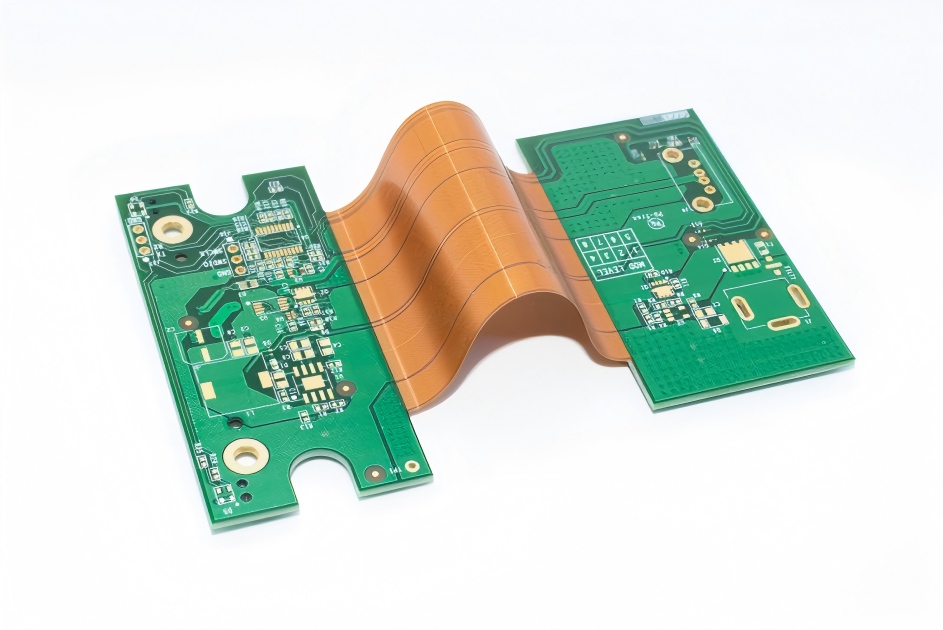
We support project evaluation for rigid-flex PCB constructions including:
- Rigid-flex PCB prototypes and engineering samples
- Multilayer rigid-flex circuit structures
- Single-sided or double-sided flexible sections integrated with rigid sections
- Multiple rigid areas connected by one or more flexible sections
- Controlled-impedance rigid-flex PCB designs
- Rigid-flex circuits with SMT components, connectors, sensors, or modules
- Flex-to-install and limited dynamic-bending applications
- Compact rigid-flex assemblies for space-constrained electronic products
Each project is reviewed according to its stack-up, layer count, material combination, flex-zone structure, copper construction, board thickness, bend requirement, surface finish, testing requirement, and production quantity.
Rigid-Flex PCB Materials and Stack-Up Review
A reliable rigid-flex PCB stack-up must provide electrical continuity, mechanical flexibility, dimensional stability, and sufficient bonding between rigid and flexible materials. Material selection should be confirmed before layout completion whenever the product has controlled impedance, tight thickness limits, repeated bending, high-temperature assembly, or demanding reliability requirements.
Typical material and stack-up considerations include:
- Polyimide flexible circuit core materials
- Adhesiveless or adhesive-based flex laminates
- Rolled-annealed or electrodeposited copper selection
- FR-4 rigid cores and prepreg materials
- Low-flow or no-flow prepreg where required by the structure
- Polyimide coverlay and coverlay opening design
- Rigid-area solder mask and legend requirements
- Finished copper thickness and plated-hole requirements
- Overall rigid-section and flexible-section thickness
- Surface finish selected for soldering, bonding, or connector contact requirements
For controlled-impedance designs, the dielectric thickness, copper thickness, trace geometry, reference-plane structure, coverlay, solder mask, and final material selection should be evaluated together.
Rigid-Flex PCB Design and DFM Review
Rigid-flex PCB manufacturability depends heavily on the transition between rigid and flexible sections. Incomplete bend information, unsuitable via placement, abrupt conductor routing, insufficient bend radius, or poorly defined stack-up data can increase the risk of copper fatigue, delamination, cracking, registration problems, or assembly interference.
Our pre-production review may include:
- Rigid-flex stack-up and material compatibility
- Flex-zone and rigid-to-flex transition design
- Minimum bend radius and intended bending direction
- Dynamic-flex versus flex-to-install operating conditions
- Trace routing through bending and transition areas
- Via, plated-hole, pad, and annular-ring placement
- Copper distribution and reference-plane design
- Coverlay openings and solder mask clearances
- Controlled-impedance structure and tolerance requirements
- Component, connector, enclosure, and mechanical interference
- Panelization, tooling, routing, and assembly fixture requirements
- Fabrication drawing consistency with Gerber and drill data
Design feedback is intended to identify practical manufacturing risks before tooling and material preparation. For additional layout guidance, review our FPC Design Guidelines.
Manufacturing and Inspection Considerations
Rigid-flex PCB production involves several interconnected processes, including flexible-core preparation, imaging, coverlay processing, rigid-flex lamination, drilling, copper plating, etching, solder mask, surface finishing, profiling, electrical testing, and final inspection.
Depending on the project specification, manufacturing and quality review may include:
- Material and stack-up verification
- Artwork and drill-data review
- Layer registration and lamination control
- Plated through-hole and via inspection
- Automated optical inspection where applicable
- Electrical continuity and isolation testing
- Finished thickness and dimensional inspection
- Surface-finish and solderability inspection
- Controlled-impedance testing when specified
- Flex-area, transition-area, and outline inspection
- Microsection or additional reliability inspection when required
Testing requirements, acceptance criteria, IPC class, inspection reports, certificates, and traceability requirements should be identified in the RFQ package whenever they are mandatory for the end application.
Rigid-Flex PCB Assembly Support
Rigid-flex PCBs may be supplied as bare circuits or evaluated together with component assembly requirements. Assembly planning should consider panel support, flexible-section protection, component placement, connector orientation, reflow conditions, mechanical fixtures, final folding, and enclosure installation.
For projects requiring component mounting or complete electronic assembly, FPCFAB can review the BOM, pick-and-place data, assembly drawing, connector requirements, soldering process, test requirements, and final mechanical configuration.
Related assembly support is available through our Flexible PCB Assembly / FPCA service.
Typical Rigid-Flex PCB Applications
Rigid-flex PCB technology is commonly selected for electronic products that require compact interconnection, controlled folding, reduced connector count, lower assembly complexity, or improved reliability in space-constrained structures.
- Automotive electronic modules and sensing systems
- Battery management and energy-storage electronics
- Medical instruments and diagnostic devices
- Industrial sensors and control modules
- Wearable and portable electronic products
- Cameras, optical modules, and imaging equipment
- Communication and networking equipment
- Aerospace, instrumentation, and specialized electronic assemblies
- Display, touch-control, and human-machine interface modules
- Compact consumer and embedded electronic devices
Files Required for a Rigid-Flex PCB Quotation
A complete quotation package helps the engineering and purchasing teams confirm manufacturability, material availability, tooling requirements, unit pricing, and lead time more accurately.
Please provide the available project information:
- Gerber, ODB++, or other production data
- NC drill and routing files
- Fabrication drawing with dimensions and tolerances
- Complete rigid-flex stack-up drawing
- Material and copper-thickness requirements
- Rigid-section and flexible-section thickness
- Bend location, bend direction, bend angle, and bend radius
- Controlled-impedance requirements and reference structures
- Surface finish, solder mask, coverlay, and legend requirements
- Netlist or electrical test requirements
- Prototype and production quantities
- Target lead time and delivery requirements
- BOM, pick-and-place file, and assembly drawing when assembly is required
- Inspection, certification, packaging, and traceability requirements
When some design information is incomplete, you may send the available drawings, photographs, samples, mechanical files, or preliminary specifications for an initial review. You can also use our FPC RFQ Requirements guide to prepare the quotation package.
Why Work With FPCFAB
- Engineering-oriented review before quotation and production
- Support for rigid-flex PCB, FPC, FPCA, and related assembly projects
- Stack-up, material, bend-area, and transition-area review
- Clear communication for international engineering and purchasing teams
- Prototype, NPI, pilot-run, and production-project evaluation
- Coordination between bare-board manufacturing and assembly requirements
- Practical feedback for incomplete or high-risk project documentation
For projects that do not require integrated rigid sections, visit our Flexible PCB Manufacturing service page.
Request a Rigid-Flex PCB Manufacturing Quote
Send us your Gerber files, stack-up drawing, fabrication drawing, bend requirements, quantities, and assembly information. Our team will review the project requirements and respond with manufacturability feedback or quotation details.