SMT assembly services support electronic products that require accurate solder paste printing, automated component placement, controlled reflow soldering, inspection, and production verification. Surface-mount assembly is commonly used for compact electronic products, fine-pitch components, high component density, prototype validation, and repeat production.
FPCFAB supports SMT assembly projects for rigid PCBs, flexible PCBs, rigid-flex PCBs, and mixed electronic assemblies. Our team can review your Gerber files, BOM, pick-and-place data, assembly drawings, component packages, soldering requirements, inspection criteria, testing requirements, and target production quantity before quotation and line preparation.
SMT Assembly Services
Surface-mount technology mounts electronic components directly onto PCB pads using solder paste, automated placement equipment, and a controlled reflow process. Successful SMT production depends on the coordination of PCB pad geometry, solder mask, stencil design, component packaging, placement accuracy, thermal balance, inspection requirements, and assembly documentation.
Project support may include:
- Prototype SMT assembly and engineering samples
- New product introduction and pilot-run assembly
- Small-batch and medium-volume SMT production
- Single-sided and double-sided component placement
- Rigid PCB, flexible PCB, and rigid-flex PCB assembly
- Fine-pitch integrated circuits and dense layouts
- Lead-free solder paste and reflow processing
- Turnkey, consigned, or mixed component sourcing
- Inspection, testing, programming, and final packaging requirements
Each project is reviewed according to board dimensions, component count, package type, minimum pitch, component density, assembly side, soldering process, inspection scope, production quantity, material availability, and required lead time.
SMT Component Package Support
Modern SMT assemblies may contain standard passive components, fine-pitch integrated circuits, bottom-terminated packages, connectors, modules, sensors, and specialized devices. Component package selection affects stencil design, placement control, reflow conditions, inspection method, and repair feasibility.
Package types may include, subject to project review:
- Resistors, capacitors, inductors, and other passive components
- SOIC, SOP, TSSOP, SOT, and similar leaded packages
- QFP and fine-pitch gull-wing components
- QFN and DFN bottom-terminated packages
- BGA, LGA, and array-style packages
- LEDs, sensors, switches, and electronic modules
- Surface-mount connectors and board-to-board interfaces
- Shielding cans, crystals, oscillators, and programmed devices
Very small passive packages, fine-pitch devices, large BGAs, unusual thermal pads, or moisture-sensitive components require review of the land pattern, stencil apertures, storage conditions, placement capability, reflow profile, and inspection method before production.
Solder Paste Printing and Stencil Review
Solder paste printing is a critical SMT process because paste volume, transfer efficiency, aperture design, board support, and printing alignment directly affect solder-joint quality. Inadequate paste deposition can cause opens, bridging, insufficient solder, component movement, voiding, or inconsistent joint formation.
Stencil and printing review may consider:
- Stencil thickness relative to component mix
- Aperture size and shape for fine-pitch packages
- Area ratio and solder-paste release conditions
- Thermal-pad and exposed-pad aperture design
- Reduced or segmented apertures where required
- Step stencil requirements for mixed component sizes
- Board support and underside component clearance
- Fiducial, tooling, and panelization requirements
- Lead-free solder paste and storage requirements
The final stencil design should be based on the approved PCB data, component land patterns, package requirements, assembly side, and solder-joint acceptance criteria.
Automated SMT Component Placement
Automated placement requires complete and consistent centroid data, reference designators, package information, component orientation, polarity markings, and feeder preparation. Inconsistent documentation can increase setup time or create placement errors during first-article production.
Placement preparation may include:
- Pick-and-place coordinate verification
- Reference-designator and BOM consistency review
- Component orientation and polarity confirmation
- Package and feeder compatibility review
- Top-side and bottom-side assembly identification
- Fiducial location and recognition requirements
- Component-to-component clearance review
- Component-to-edge and tooling-clearance review
- Manual placement planning for special components
Assembly drawings should clearly identify polarity, pin-one direction, connector orientation, special mounting requirements, do-not-populate locations, and any components requiring manual handling.
Reflow Soldering Process
Reflow soldering heats the populated PCB through controlled temperature zones to activate the flux, melt the solder alloy, form solder joints, and cool the assembly. The appropriate thermal profile depends on board thickness, copper distribution, component thermal mass, solder paste, package type, moisture sensitivity, and component temperature limits.
Reflow planning may consider:
- Lead-free or project-specific solder alloy
- Preheat, soak, reflow, and cooling requirements
- Peak component temperature limitations
- Thermal balance across dense or mixed-component areas
- Large ground pads and exposed thermal pads
- BGA, QFN, LGA, and bottom-terminated devices
- Double-sided assembly process sequence
- Moisture-sensitive component preparation
- Board warpage and support requirements
Special temperature restrictions, sensitive components, selective soldering exclusions, or customer-defined thermal-profile requirements should be included in the assembly documentation.
AOI, X-Ray, and Visual Inspection
Inspection requirements should be selected according to component type, solder-joint visibility, product reliability, board complexity, and customer acceptance criteria. No single inspection method can confirm every possible assembly condition.
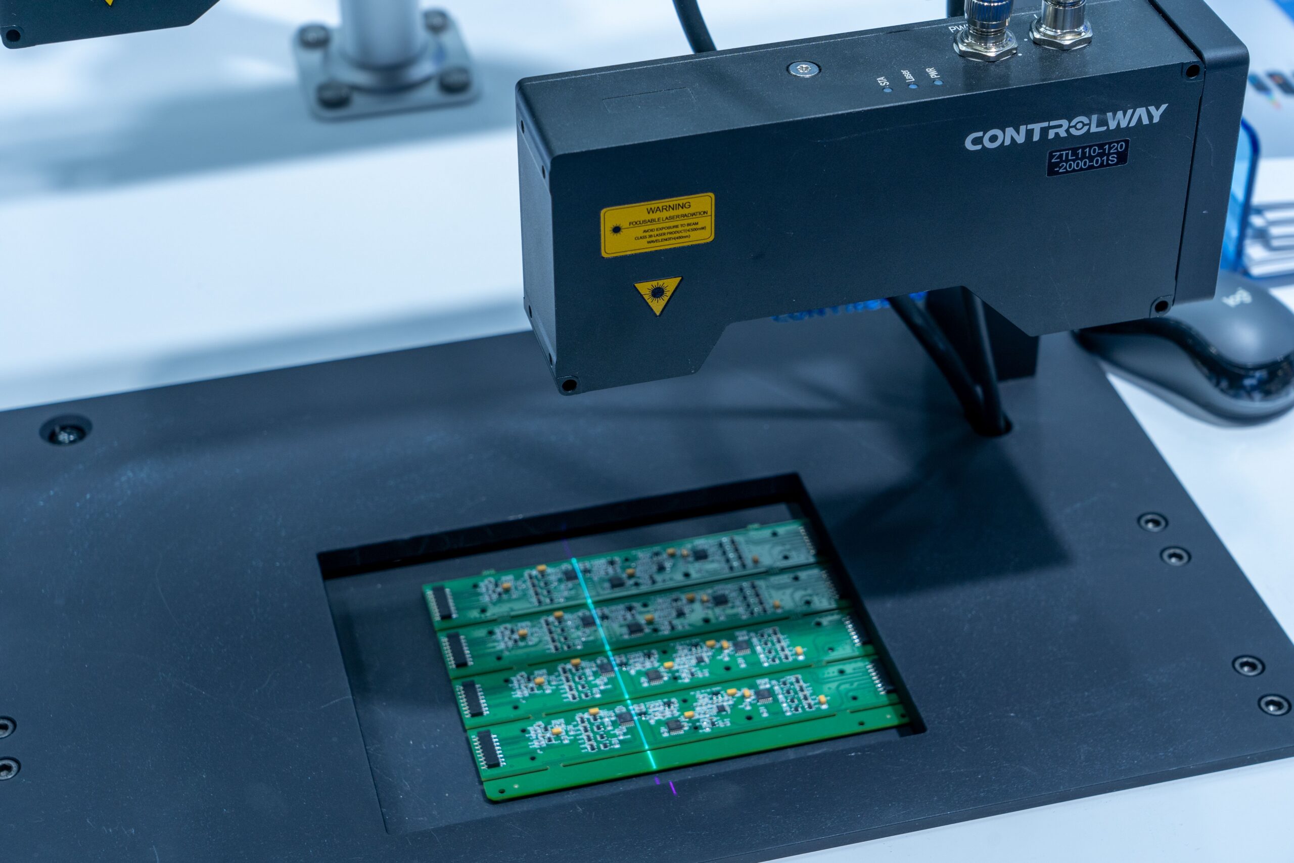
Inspection may include:
- First-article component and polarity verification
- Automated optical inspection where applicable
- Visual solder-joint and workmanship inspection
- Component presence, offset, rotation, and polarity checks
- Solder bridging and insufficient-solder inspection
- X-ray inspection for BGA, QFN, LGA, or hidden joints when specified
- Connector, mechanical-part, and component-height inspection
- Final cleaning, labeling, and quantity verification
X-ray inspection can help evaluate hidden solder joints, voiding, bridging, insufficient solder, and alignment beneath bottom-terminated components. Acceptance limits and reporting requirements should be defined before quotation when X-ray documentation is required.
SMT Assembly DFM Review
SMT DFM review identifies practical assembly risks before stencil preparation, component purchasing, and line setup. It is especially important for new designs, fine-pitch components, dense layouts, mixed package sizes, incomplete documentation, and unusual mechanical requirements.
Pre-production review may include:
- Gerber, board outline, and drill-data consistency
- BOM, centroid, and assembly-drawing consistency
- Pad geometry and solder mask definition
- Stencil-aperture and solder-paste considerations
- Fine-pitch component and connector clearances
- Component orientation and polarity markings
- Panelization, tooling rails, and fiducials
- Board support during printing and placement
- Thermal balance and reflow-process risks
- Test-point accessibility and fixture requirements
- Mechanical, enclosure, connector, and cable interference
For flexible PCB bend areas, stiffeners, coverlay openings, stack-up, or mechanical integration, review our FPC Design & DFM Review service.
Prototype and Small-Batch SMT Assembly
Prototype SMT assembly is used to verify component selection, PCB layout, solderability, electrical performance, firmware, testing, enclosure fit, and production feasibility before larger quantities. Early builds often require additional engineering communication because BOMs, assembly drawings, or test procedures may still be changing.
Prototype and production preparation may include:
- Engineering samples and first-article assembly
- Design-validation and verification builds
- New product introduction and pilot runs
- Controlled small-batch SMT production
- Repeat production using approved documentation
- Revision control for Gerber, BOM, and centroid data
- Component traceability and material preparation
- Packaging and shipment planning
For broader assembly projects that include through-hole components, connectors, cables, testing, programming, and mechanical integration, review our PCB Assembly / PCBA service.
Flexible PCB and Rigid-Flex SMT Assembly
SMT placement on flexible and rigid-flex circuits requires additional attention to panel support, local stiffening, flexible-area protection, component placement, reflow handling, depaneling, final folding, and mechanical installation.
Project considerations may include:
- Stiffener support beneath component areas
- Fixture support for thin flexible sections
- Protection of flex tails and bend regions
- Component placement outside critical bend areas
- Connector orientation and final insertion direction
- Panelization and depaneling requirements
- Final folding and enclosure installation
- Packaging that protects flexible sections after assembly
Flexible-circuit assembly projects can also be evaluated through our Flexible PCB Assembly / FPCA service.
Files Required for an SMT Assembly Quotation
A complete RFQ package helps confirm component availability, assembly feasibility, tooling requirements, inspection scope, production cost, and lead time more accurately.
Please provide the available project information:
- Gerber, ODB++, or approved PCB production data
- NC drill and board-outline files
- Complete BOM with manufacturer part numbers
- Pick-and-place or centroid data
- Assembly drawing with polarity and orientation information
- PCB fabrication drawing and stack-up when available
- Approved component alternatives, if permitted
- Prototype and production quantities
- Turnkey, consigned, or mixed sourcing preference
- Inspection, testing, and programming requirements
- Firmware files and programming instructions when applicable
- Panelization, tooling, and depaneling requirements
- Packaging, labeling, and traceability requirements
- Target lead time and delivery destination
If some documentation is incomplete, send the available Gerber data, BOM, drawings, photographs, component information, or reference samples for an initial review.
Why Work With FPCFAB
- Engineering-oriented review before quotation and production
- Support for rigid PCB, flexible PCB, and rigid-flex SMT projects
- BOM, Gerber, centroid, and assembly-file consistency review
- Prototype, NPI, pilot-run, and small-batch evaluation
- Coordination between PCB fabrication and SMT assembly
- Practical communication for overseas engineering and purchasing teams
- Clear identification of component, process, and documentation risks
Request an SMT Assembly Quote
Send us your Gerber files, BOM, pick-and-place data, assembly drawings, quantities, component-sourcing preferences, inspection requirements, and testing information. Our team will review the project documentation and respond with manufacturing questions, component considerations, or quotation details.