An FPC assembly drawing review is not just a check of where parts go. It is the human-readable control layer that should agree with the BOM, centroid or placement data, approved component package drawings, fabrication data, and the intended product variant. When those sources disagree, an assembler may still be able to generate a machine program, but the program may faithfully build the wrong configuration.
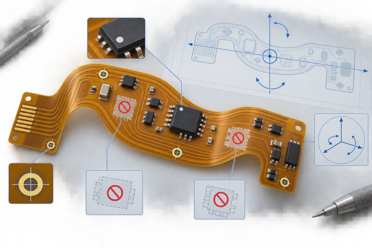
This guide explains how to review polarity, rotation, fiducials, and do-not-populate (DNP) control before an FPC assembly package is released. It does not impose a universal zero-degree convention, fiducial count, or marking rule. Those details depend on the CAD system, component package, assembly process, panel format, and the project-matched manufacturing partner.
Start with one controlled assembly definition
A drawing review should begin with configuration, not graphics. Record the assembly number, revision, variant, side designations, and release date. Then identify every file that is expected to describe that same configuration: BOM, placement file, assembly drawing, schematics, intelligent product model if supplied, and any approved deviation list.
IPC-D-325A remains an IPC reference for assembly drawings and parts lists in the documentation areas that IPC says have not been superseded. IPC-2231 provides a broader DFX framework for disciplined, multidisciplinary review. The practical lesson is simple: the drawing cannot be approved in isolation. It must be checked as part of a coherent manufacturing data set.
Define the authority of each file
Many avoidable questions arise because the package does not say which file governs. A useful release note can define, for example, that the BOM controls approved manufacturer part numbers, the placement data controls X/Y and machine rotation, and the assembly drawing controls visual orientation, special notes, and DNP identification. If an intelligent format such as IPC-2581 or ODB++Design is supplied, its revision and role should also be stated.
Intelligent formats can carry far more than copper images. IPC-2581 supports assembly description, BOM, revision history, library orientation, and product variants. ODB++Design likewise packages manufacturing-oriented design information. These formats can reduce manual re-entry, but they do not remove the need to confirm that the exported dataset matches the released drawing and BOM.
Polarity: verify the package, land pattern, and visible cue
Polarity review should answer three different questions. First, what is the electrical orientation required by the schematic and pin assignment? Second, how is that orientation represented in the CAD land pattern and assembly data? Third, what physical feature on the supplied component allows an operator or inspection system to recognize it?
Do not assume every package uses the same dot, chamfer, bar, notch, or text direction. Manufacturer package drawings can define different indicators and may show top or bottom views. The device datasheet or current manufacturer package specification should take precedence over an informal visual assumption. A concise drawing callout should identify the relevant pin, cathode, anode, positive terminal, or other functional orientation without relying only on body-print direction.
IPC-7352 provides current generic land-pattern guidance and explicitly directs designers to the component manufacturer’s datasheet for specific package dimensions. That boundary matters here: a standard land-pattern family is not proof that a particular orderable device uses the expected marking or terminal map.
Polarity review questions
- Does every polarized reference designator have an unambiguous drawing cue?
- Does that cue agree with the approved manufacturer datasheet and exact package option?
- Are top-view and bottom-view drawings clearly distinguished?
- Does the land-pattern pin numbering agree with the schematic symbol and placement export?
- Can the cue still be inspected after nearby parts, stiffeners, shields, or connectors are installed?
Rotation: define the coordinate system before checking angles
A rotation value is meaningful only inside a defined coordinate system. Different ECAD tools, libraries, exporters, and placement systems may use different zero orientations, positive directions, and bottom-side transformations. Therefore, “R = 90°” is not self-explanatory unless the package states the datum, viewing side, and rotation convention.
The safest review compares at least three representations: the visual assembly drawing, the centroid or placement file, and the component land-pattern definition. For asymmetric packages, add the manufacturer’s pin diagram. Check representative parts at 0°, 90°, 180°, and 270° on each populated side. Then check any component whose body outline is symmetrical but whose electrical orientation is not.
Rotation review is especially important on flexible assemblies because the board may be supplied flat, panelized, supported on a carrier, or formed later. The assembly drawing should show the manufacturing view used for placement and separately identify any final installed shape when that distinction affects interpretation. IPC-2223 addresses design requirements specific to flexible and rigid-flexible printed boards, but project-specific tooling and handling still require supplier confirmation.
Fiducials: connect the drawing to the assembly strategy
Fiducials give imaging and placement systems optical references for translation, rotation, and—where the process uses them—local compensation. The drawing review should distinguish panel fiducials, board-level fiducials, and local fiducials near critical packages. It should also distinguish intentional fiducials from test pads, tooling features, exposed copper, or decorative targets.
Avoid publishing a fixed fiducial count or universal geometry unless it has been agreed for the actual equipment and panel strategy. Instead, review whether the selected references are present in the fabrication data, remain visible in the assembled panel or carrier condition, have the intended surface and mask clearance, and are not covered by stiffeners, adhesive, labels, shields, or temporary support materials.
On an FPC, local deformation and carrier design can affect how the assembly is presented to imaging systems. The drawing should therefore identify the assembly datum and reference features in the same physical state used for programming and verification. If local fiducials are omitted, the decision should be based on package, board, process, and partner review—not on a generic assumption that global references are always sufficient.
DNP control: treat absence as configuration data
DNP is not a casual note. It is a population state tied to a specific variant and revision. A robust package uses one consistent identifier—DNP, DNI, NP, or another defined term—and maps that state to the same reference designators across the BOM, drawing, placement data, and intelligent product model.
The most dangerous condition is not a clearly marked empty footprint. It is a mixed message: the BOM says DNP, the drawing shows a fitted outline, and the placement file still contains coordinates. The assembler then has to guess whether the placement entry is intentional for an alternate variant or simply a stale export.
| Review item | Acceptable evidence | Escalate when |
|---|---|---|
| Variant identity | Assembly number, revision, and variant are consistent across released files | A file is undated, differently revised, or names another option |
| DNP list | One controlled list maps every excluded reference designator | Drawing, BOM, and placement export disagree |
| Substitute status | Approved alternates remain separate from population state | “DNP” is being used to mean unavailable or not yet sourced |
| Future-use footprints | Empty locations are intentionally documented | Unlisted empty pads could be interpreted as missing parts |
| Inspection basis | Expected fitted and empty locations can be derived from released data | No controlled golden configuration exists |
Do not delete DNP references from one file merely to make the package look cleaner. Keeping the reference designator visible can preserve traceability between schematic, layout, variants, inspection, and future revisions. Whether DNP locations remain in the machine file is a workflow decision that should be explicitly agreed and controlled.
A practical FPC assembly drawing review sequence
- Freeze the review set. List filenames, revisions, checksums or release identifiers, variant, and date.
- Confirm the viewing convention. Identify top, bottom, manufacturing state, origin, axes, units, and positive rotation direction.
- Reconcile reference designators. Compare the drawing, BOM, placement data, and schematic for missing or duplicated references.
- Audit polarized parts. Use the exact manufacturer package documentation, not a generic library thumbnail.
- Sample rotations systematically. Include each quadrant, both sides, asymmetric packages, and electrically asymmetric packages with symmetric bodies.
- Review fiducials in context. Confirm their type, visibility, fabrication definition, carrier/panel relationship, and process ownership.
- Reconcile DNP states. Produce one variant-specific list and resolve every mismatch before program release.
- Close open items. Record the question, affected files and references, decision owner, disposition, and resulting revision.
This sequence complements the broader release controls described in our FPC assembly RFQ checklist. After the data package is aligned, the inspection plan should still define how orientation and population are verified; see the FPC assembly inspection guide. For dense layouts, the review should also consider access, support, and inspection constraints discussed in fine-pitch FPC assembly planning.
What to send for an engineering review
A useful review package normally includes the assembly drawing, BOM, centroid or placement file, fabrication data, schematic, approved part datasheets for ambiguous packages, variant matrix, and a short list of known open items. Native or intelligent design data can help when available, but the exact accepted formats and review depth are subject to confirmation with the project-matched manufacturing partner.
FPCFAB can organize project inputs and coordinate drawing, sourcing, quotation, and assembly questions with a project-matched manufacturing partner. It does not replace the product owner’s design authority, and it does not imply fixed process capability, equipment, tolerance, inspection scope, price, or lead time. Those items must be confirmed for the released project data.