Rigid-flex PCB assembly succeeds when the flat manufacturing data, the SMT process, and the final three-dimensional installation are treated as one controlled project. The assembly team needs more than Gerber files and a BOM: it needs a clear definition of rigid zones, flex zones, bend intent, support method, forming sequence, acceptance criteria, and the evidence required after the board reaches its installed shape.
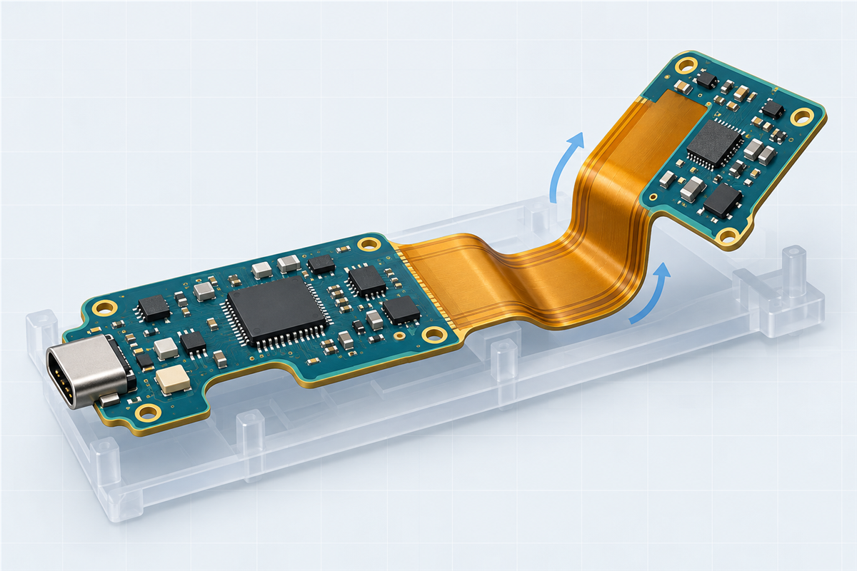
1. Define the Rigid-Flex Use Before Assembly DFM
The first question is not stencil thickness or placement speed. It is how the flexible section will be used. IPC-6013E covers qualification and performance requirements for flexible and rigid-flex printed boards and distinguishes flex during installation from continuous flexing specified by cycle count. It also requires the relevant performance class and installation usage to be stated in procurement documentation.
That distinction changes the design review. A flex-to-install circuit may be formed once or a limited number of times during product assembly. A dynamic application needs a defined motion, bend direction, cycle expectation, environmental condition, and validation method. The two cases should not share an assumed bend rule or a copied test plan.
Flex-to-install
Define the flat delivery state, installation path, final shape, allowed handling, bend direction, and any forming fixture. Verify electrical continuity after the actual forming step.
Repeated movement
Define motion limits, cycle target, minimum operating radius, neutral routing, enclosure constraints, and the test method. Treat these as product requirements, not assembler assumptions.
2. Freeze the Mechanical Boundaries
IPC-2223E is the sectional design standard for flexible and rigid-flex printed boards. Its scope includes component mounting and interconnecting structures, and its contents explicitly address palletization, moisture, reflow, component placement, mounting constraints on flexible sections, interfacial connections, and documentation.
For assembly release, the drawing or mechanical layer should identify every rigid area, flexible area, flex-to-rigid transition, bend zone, bend direction, final orientation, connector datum, and enclosure-critical clearance. If the 2D drawing and the 3D model disagree, the project needs a documented source of truth and a revision correction before tooling.
- Keep component pads, vias, test pads, and mechanical holes out of the active bend zone unless the construction and use have been specifically reviewed and qualified.
- Avoid abrupt conductor-width or direction changes inside the bend; use smooth routing and review copper balance across the flexible section.
- Define clearance between component bodies, stiffeners, coverlay edges, rigid-flex transitions, and the installed enclosure.
- Show the connector mating direction and the forces expected during insertion, removal, fastening, or cable handling.
The 2025 Würth Elektronik Flex Solutions design guide provides a useful supplier example: it recommends a dedicated mechanical layer for rigid and flex areas and keeping vias and pads out of bending areas. Its numerical design rules apply to its own technology families, so they should not be copied as universal limits. Final geometry remains subject to the selected fabricator’s reviewed stack-up and process.
3. Build One Controlled Assembly Package
Rigid-flex projects often fail at document interfaces rather than at a single manufacturing operation. One team owns the PCB data, another owns the assembly drawing, and a third owns the enclosure. The release package must connect those datasets through common revisions and datums.
| Document | Minimum useful content | Risk if missing |
|---|---|---|
| Fabrication package | Approved artwork data, stack-up, materials or performance requirements, surface finish, outline, rigid/flex boundaries, controlled dimensions, and applicable acceptance requirements | The bare board may not match assembly tooling or the installed mechanical state. |
| Assembly drawing | Reference designators, polarity, side, no-fit parts, connector orientation, adhesive or hardware notes, and special workmanship requirements | Correct parts can be placed in the wrong orientation or sequence. |
| BOM and component data | Manufacturer part number, approved alternatives, quantity, package, lifecycle notes, moisture sensitivity where applicable, and customer-supplied items | Sourcing substitutions can change land compatibility, height, mass, or reflow limits. |
| Placement data | X/Y coordinates, rotation convention, side, origin, units, and a visual centroid verification | Rotation or origin errors can survive automated import checks. |
| Mechanical definition | Flat view, installed 3D view, bend zones, bend direction, final envelope, connector datum, and forming sequence | A flat board may pass test but interfere or overstress during installation. |
| Test and release plan | Electrical test coverage, functional test responsibility, mechanical checks, acceptance class, records, and sample or lot requirements | “Tested” remains ambiguous and evidence may not support release. |
4. Plan Support, Printing, and Placement as a System
A rigid-flex board may contain self-supporting rigid islands, but the overall assembly can still sag, twist, or sit at different heights during printing and placement. The process review should therefore cover the delivery panel, tooling rails, fiducials, support pins, carrier pockets, vacuum access, bottom-side components, and the method used to retain the board without loading the flex transitions.
The carrier concept and paste process cannot be selected independently. A pocket deep enough to clear a rigid section or bottom-side component may change stencil access or squeegee support. A carrier opening may enable two-sided assembly but can also require a project-specific printing approach. These details are line- and product-dependent and must be confirmed with the project-matched manufacturing partner.
- Confirm the flat support plane and how each rigid island is located.
- Define global and local fiducials that remain visible in the actual carrier.
- Review stencil access, paste aperture data, board steps, and any bottom-side clearance.
- Check nozzle access, component height, camera view, and collision risk at transitions.
- Approve depanelization and carrier-release methods before the first assembled lot.
For a broader discussion of panelization, stencil printing, placement, and reflow on flexible circuits, see the FPC Assembly DFM Guide. The rigid-flex review adds the need to coordinate multiple rigid islands and the final three-dimensional state.
5. Control Thermal History and Material Handling
A generic reflow profile is not a complete instruction. The approved process must account for the solder paste, component limits, board construction, copper distribution, component mass, carrier, oven, and any repeated thermal exposures. The unpopulated board qualification requirement and the populated assembly acceptance requirement are related but not interchangeable.
IPC identifies J-STD-001J as the industry-consensus standard for soldering processes and materials, while IPC-A-610J addresses post-assembly acceptance. The purchase documents should state the applicable revision, class, customer exceptions, and required objective evidence rather than using “IPC compliant” as an undefined phrase.
Moisture handling also needs a named owner. The Würth guide requires drying before soldering for its flexible and rigid-flex PCB products and notes that the parameters depend on board design, equipment, material, and soldering process. That is a supplier-specific instruction, not permission to invent a universal bake cycle. Obtain the bare-board supplier’s packaging, storage, and drying instructions, then have the assembler incorporate the approved method and exposure limits into the traveler.
6. Protect Connectors and Solder Joints During Forming
Connectors, large components, and fasteners create local stiffness and insertion forces. Their placement should be reviewed against the nearest flex transition, the mating direction, the enclosure datum, and the support available during product assembly. If an operator must pull the flex section to mate a connector, the process may transfer load into pads, solder joints, or the rigid-flex boundary.
Define whether forming occurs before electrical test, after electrical test, or both. A useful sequence often includes a flat-state check, controlled forming with an approved tool or fixture, a post-form continuity check, and final functional or interface verification. The actual sequence depends on access, test coverage, component fragility, and product architecture.
The FPC Assembly Inspection Guide explains how to match AOI, X-ray, electrical, and functional testing to the defects or requirements each method can actually verify.
7. Use a Stage-Gate Release Plan
| Gate | Decision | Evidence to retain |
|---|---|---|
| Design release | Rigid/flex boundaries, bend intent, stack-up, connector datums, and installed envelope agree. | Approved fabrication drawing, assembly drawing, 3D view, and revision record |
| Process release | Panel or carrier, stencil, placement, thermal process, separation, and forming sequence are feasible. | DFM response, tooling drawing, approved process notes, and unresolved-item closure |
| First-build release | Placement, soldering, hidden-joint coverage, continuity, and mechanical fit meet the defined criteria. | Inspection/test report, first-article photos if required, and deviation record |
| Production release | Approved files, components, tooling, test program, and process revisions are controlled. | Configuration list, change approvals, lot records, and nonconformance disposition |
Rigid-Flex PCB Assembly RFQ Checklist
Send the following information before quotation whenever it is available. Missing items can be identified as open questions, but they should not be silently assumed.
- Gerber, ODB++, or other agreed fabrication data with a revision identifier
- Fabrication drawing and proposed rigid-flex stack-up
- Assembly drawing, BOM, pick-and-place data, and paste-layer data
- Flat and installed mechanical views with bend zones and connector datums
- Flex-to-install or repeated-movement definition, including required validation
- Surface finish, component packages, approved substitutions, and customer-supplied parts
- Required acceptance class, inspection scope, electrical/functional test, and records
- Prototype and expected production quantities, target schedule, and packaging requirements
If the bend geometry is still under review, the FPC Bend Radius Design Guide provides a structured way to separate static, flex-to-install, and dynamic conditions before selecting a project-specific limit.
Prepare the Project Before Tooling
FPCFAB can organize the available rigid-flex PCB assembly files and coordinate fabrication, assembly, DFM, quotation, and production follow-up with a project-matched manufacturing partner. Materials, tooling, process limits, inspection, testing, cost, and schedule remain subject to review and confirmation for the actual project.