FPC bend radius cannot be defined reliably by using one universal thickness multiplier for every flexible circuit. The required radius depends on the complete construction, including the flexing condition, finished thickness, layer count, copper foil type, plated copper buildup, conductor geometry, coverlay, shielding, stiffeners, bend direction, operating temperature, and expected flex life.
A circuit that is bent once during product installation can normally tolerate a different mechanical condition from an FPC that moves continuously in a hinge, robotic mechanism, printer assembly, wearable device, camera module, or medical instrument. Treating these applications as equivalent can lead to copper cracking, intermittent opens, coverlay delamination, conductor necking, stiffener-edge failure, or unstable impedance.
The purpose of bend-radius design is not simply to prevent the circuit from folding too tightly. It is to control strain in the copper and surrounding dielectric structure over the required service life.
This guide explains how engineering teams should evaluate static-flex, installation-flex, limited-cycle, and dynamic-flex applications before finalizing the FPC stack-up and production data.
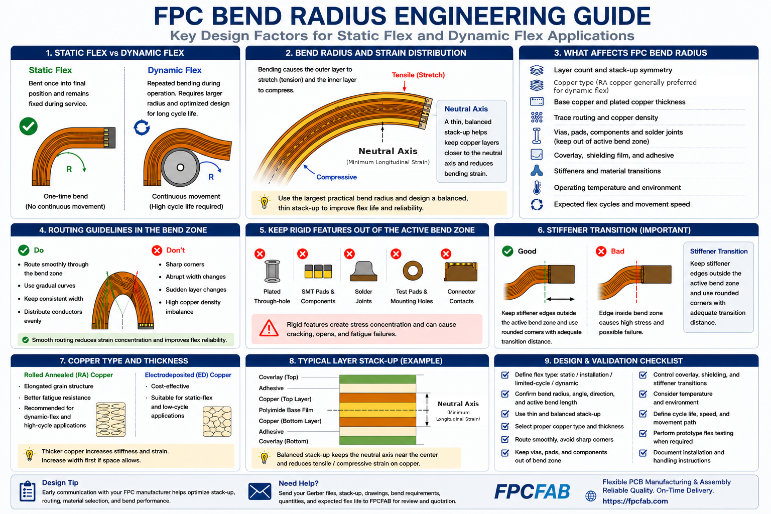
1. FPC Bend Radius: Why One Rule Does Not Fit Every Design
Published bend-radius guidelines are useful as initial screening values, but they should not be treated as guaranteed design limits. Two flexible circuits with the same nominal finished thickness may behave differently if one uses rolled annealed copper and the other uses electrodeposited copper, or if one includes plated through-holes, shielding film, several coverlay layers, and local stiffeners.
For industry design guidance applicable to flexible printed boards, refer to the IPC-2223 sectional design standard.
The minimum practical bend radius is influenced by:
- Static, installation, limited-cycle, or dynamic flexing
- Total finished thickness in the active bend region
- Single-layer, double-layer, or multilayer copper construction
- Rolled annealed or electrodeposited copper foil
- Base copper and plated copper thickness
- Adhesive-based or adhesiveless laminate
- Bend direction relative to the copper layers and conductor routing
- Coverlay, shielding film, pressure-sensitive adhesive, and local reinforcement
- Operating temperature and environmental exposure
- Expected bend cycles and movement speed
The correct design decision therefore begins with the application. The manufacturer cannot confirm a meaningful bend radius unless the customer defines how the circuit will be installed and how it will move during service.
General FPC layout considerations are covered in our FPC Design Guidelines.
2. Static Flex, Installation Flex, Limited-Cycle Flex, and Dynamic Flex
Flexible circuits are often described as either static or dynamic, but many real applications fall between these two categories. A practical engineering review should distinguish at least four operating conditions.
Static Flex
A static-flex circuit is bent into its final installed position and then remains substantially fixed. The circuit may experience vibration, thermal expansion, or occasional service movement, but repeated bending is not part of normal operation.
Static-flex applications may allow a more robust construction than continuous-motion applications, but the installation bend still requires control. A circuit can be damaged during assembly even if it never moves again after installation.
Installation Flex
Installation-flex describes an FPC that is bent, folded, or formed during product assembly. The circuit may be manipulated several times before reaching its final position.
The engineering drawing should define the intended fold line, bend direction, available space, installation sequence, and whether the assembly operator uses a fixture or performs the bend manually.
Limited-Cycle Flex
Some products move only during maintenance, adjustment, opening, or occasional operation. These applications may require tens, hundreds, or several thousand cycles rather than continuous high-cycle motion.
Limited-cycle designs still require defined cycle life and test conditions. Without this information, the supplier may incorrectly evaluate the circuit as static flex.
Dynamic Flex
A dynamic-flex circuit bends repeatedly during normal product operation. Typical applications include moving print heads, camera mechanisms, robotics, wearable products, medical equipment, hinges, and rotating or translating assemblies.
Dynamic-flex design requires the most careful control of construction thickness, copper foil, conductor orientation, routing geometry, bend radius, neutral-axis location, shielding, and transition areas. Prototype flex testing is often required before volume production.
| Flexing Condition | Typical Movement | Primary Engineering Concern |
|---|---|---|
| Static flex | One-time bend into a fixed position | Installation damage and long-term stress at the final bend |
| Installation flex | Several bends during product assembly | Assembly sequence, operator handling, and fold-line control |
| Limited-cycle flex | Occasional service or adjustment movement | Defined cycle life and repeatable motion geometry |
| Dynamic flex | Continuous or frequent repeated movement | Copper fatigue, strain distribution, friction, and cycle-life validation |
3. Finished Thickness and Strain Distribution
Finished thickness is one of the strongest influences on bending strain. As the construction becomes thicker, the outer layers travel through a greater change in length during bending. This increases tensile strain on the outside of the bend and compressive strain on the inside.
The thickness review should include every material present in the active bend region:
- Polyimide base film
- Base copper foil
- Plated copper
- Adhesive layers
- Coverlay film and coverlay adhesive
- Bondply or bonding film
- Shielding film or copper shield
- Pressure-sensitive adhesive
- Local reinforcement or overlap from transition regions
Nominal laminate thickness alone is therefore not sufficient. The actual finished construction in the bend region should be evaluated.
4. Neutral Axis and Stack-Up Symmetry
The neutral axis is the region within the bent construction that experiences minimal longitudinal strain. Copper positioned closer to this region is generally subjected to less tensile or compressive strain than copper located near the outer surfaces.
In a simple symmetrical construction, the neutral axis may be near the geometric center. In a real FPC, however, the position can shift because the layers have different thicknesses and mechanical properties.
Factors that can shift or disturb the neutral axis include:
- Asymmetrical copper distribution
- Different coverlay constructions on each side
- Single-sided shielding film
- Local adhesive or reinforcement layers
- Unequal dielectric thickness
- Stiffener overlap into the bend transition
Dynamic-flex constructions generally benefit from thin, balanced, and mechanically symmetrical stack-ups. However, electrical, shielding, assembly, and connector requirements may prevent perfect symmetry. The final design should therefore be reviewed as a complete mechanical structure.
5. Copper Foil Type, Copper Thickness, and Plating
Copper behavior is central to flex reliability. The supplier should review the base foil type, copper thickness, grain direction, plated copper distribution, conductor geometry, and expected cycle life.
Rolled Annealed Copper
Rolled annealed copper is commonly selected for dynamic-flex applications because its elongated grain structure generally provides better resistance to repeated bending than standard electrodeposited copper.
RA copper alone does not guarantee long flex life. Thick copper, tight radii, heavy plated buildup, poor routing, and abrupt material transitions can still cause premature failure.
Electrodeposited Copper
Electrodeposited copper can be suitable for many static-flex and cost-sensitive designs. Its suitability depends on foil grade, thickness, application condition, and manufacturing process.
Copper Thickness
Thicker copper increases current-carrying capability but also increases bending stiffness and strain. For bend areas, increasing conductor width may be mechanically preferable to increasing copper thickness when space permits.
Plated Copper Buildup
Plated copper around through-holes and on conductor surfaces can increase local thickness and reduce flexibility. The actual finished copper construction should be considered, not only the starting foil thickness.
Plated holes should generally be excluded from active dynamic bend zones because the barrel, annular ring, and surrounding plated copper create a local stiffness and stress concentration.
6. Trace Routing Through the Active Bend Zone
Trace geometry should distribute strain gradually through the bend. The active bend zone should not contain unnecessary geometric discontinuities.
Recommended routing principles include:
- Route conductors smoothly through the bend region
- Avoid sharp corners and abrupt direction changes
- Maintain consistent conductor width where practical
- Use gradual width transitions when a change is necessary
- Avoid sudden copper-density changes
- Distribute conductors evenly across the flex width
- Avoid stacking conductors directly above one another in demanding multilayer dynamic-flex regions when the electrical design allows staggering
- Confirm routing direction relative to the bend axis
Conductors are commonly routed generally perpendicular to the bend axis so that the bend occurs along the conductor length rather than creating a concentrated lateral distortion. The exact routing should be reviewed against the actual motion path.
Solid copper planes can make a bend region excessively stiff. Crosshatched copper may improve flexibility and maintain shielding or reference-plane functions, but hatch geometry, orientation, impedance, and manufacturing capability must be evaluated together.
7. Vias, Pads, Components, and Solder Joints
Active bend zones should remain free from rigid or highly localized features whenever possible. These features interrupt uniform strain distribution and can become crack initiation points.
Features normally kept outside the active bend zone include:
- Plated through-holes
- Blind or buried vias
- SMT pads
- Component bodies
- Solder joints
- Test pads
- Connector contacts
- Mechanical mounting holes
When these features cannot be avoided, the design requires a controlled local reinforcement strategy and application-specific validation. Simply adding a stiffener does not eliminate stress; it moves the transition to another location.
8. Coverlay, Stiffeners, and Material Transitions
Many flex failures occur near material transitions rather than at the center of a smooth bend. Coverlay terminations, stiffener edges, adhesive boundaries, shielding-film edges, rigid-flex transitions, and local thickness changes can create abrupt stiffness differences.
Coverlay
Coverlay should provide conductor protection without creating unnecessary thickness or abrupt edges in the moving area. The coverlay opening pattern and lamination condition should avoid exposed copper or adhesive contamination near the bend.
Stiffeners
Stiffeners are normally used under connectors, component areas, contact fingers, mounting holes, and insertion zones. Their edges should not terminate inside a high-strain bend region.
The transition from a stiffened area to an unsupported flex area should be positioned where the circuit can change stiffness gradually. Rounded stiffener corners, suitable overlap, controlled adhesive thickness, and adequate distance from the active bend can reduce local stress concentration.
Rigid-Flex Transitions
Rigid-flex constructions require careful control of coverlay termination, rigid material edge geometry, copper routing, plated-hole locations, and lamination structure near the rigid-to-flex transition. This region should not be treated as a normal free-flex bend.
9. Shielding and Controlled-Impedance FPCs
Shielding and impedance requirements can significantly change bend behavior. Conductive shielding film, copper shielding, ground layers, and reference planes add material and stiffness to the flexible structure.
For shielded FPCs, review:
- Shielding material type
- Number of shielded sides
- Grounding and termination method
- Shielding-film overlap and edge location
- Local thickness increase
- Effect on bend stiffness and cycle life
Controlled-impedance routing must maintain the required electrical relationship while the circuit remains mechanically reliable. Differential-pair spacing, conductor width, dielectric thickness, reference-plane structure, coverlay, and shielding should be evaluated together.
A design that meets the target impedance while flat may still experience mechanical damage if the stack-up is too stiff for the required movement. Electrical and mechanical requirements must therefore be balanced during DFM review.
10. Bend Direction, Assembly Sequence, and Installation Control
The installation drawing should define the bend direction and motion path. Bending an FPC in the opposite direction from the intended design can place copper layers under a different strain condition.
Assembly instructions should identify:
- Intended bend line
- Inside and outside of the bend
- Minimum installation radius
- Permitted folding or forming sequence
- Areas that must not be creased
- Required forming fixture or mandrel
- Handling restrictions for contact fingers and component areas
Even a mechanically sound FPC can be damaged by uncontrolled manual folding, repeated adjustment during assembly, use of a sharp tool edge, or forcing the circuit into an enclosure with insufficient clearance.
11. Prototype Validation and Flex-Cycle Testing
For high-cycle or safety-critical applications, design rules alone are not sufficient. Prototype testing should reproduce the actual bend radius, movement path, temperature, speed, dwell time, and mechanical constraints as closely as practical.
A flex test plan may define:
- Bend radius
- Bend angle
- Movement direction
- Cycle rate
- Total cycle count
- Operating temperature
- Electrical load or monitoring current
- Acceptable resistance change
- Inspection intervals
- Failure criteria
Electrical monitoring can identify intermittent conductor failure before a complete open circuit develops. Post-test inspection may include visual examination, dimensional review, resistance measurement, cross-sectioning, or microscopy depending on the failure mode.
Test results should be interpreted against the actual product requirement. A test that uses a larger radius, slower movement, lower temperature, or different constraint condition may not represent field performance.
12. Information Required for FPC Bend-Radius Review
To evaluate FPC bend radius and flex reliability, provide the manufacturer with the following information whenever available:
- Static, installation, limited-cycle, or dynamic-flex classification
- Target bend radius
- Bend angle and bend direction
- Location and length of the active bend zone
- Expected cycle count
- Cycle rate and movement path
- Operating and storage temperature
- Layer stack-up and finished thickness
- Copper foil type and copper thickness
- Coverlay, shielding, and stiffener construction
- Connector, component, and solder-joint locations
- Installation drawing or 3D mechanical model
- Available prototype test data
When these details are not yet finalized, the supplier can provide preliminary DFM feedback, but the final bend capability should not be approved until the real operating condition is defined.
FPC Bend-Radius DFM Checklist
| Review Item | Questions to Confirm |
|---|---|
| Flex classification | Is the circuit static flex, installation flex, limited-cycle flex, or dynamic flex? |
| Bend geometry | What are the radius, angle, direction, active bend length, and movement path? |
| Stack-up | Are the finished thickness, layer symmetry, dielectric system, and copper construction suitable? |
| Copper | Are copper foil type, base thickness, plating buildup, and conductor geometry appropriate? |
| Routing | Are traces smooth, balanced, and free from abrupt width or direction changes? |
| Rigid features | Are vias, pads, components, solder joints, test points, and mounting holes outside the active bend? |
| Transitions | Are coverlay edges, stiffener edges, shielding boundaries, and rigid-flex transitions controlled? |
| Electrical performance | Do shielding and controlled-impedance requirements remain compatible with mechanical movement? |
| Assembly | Are bend direction, installation sequence, tooling, and handling restrictions documented? |
| Validation | Does the test plan reproduce the real radius, cycle count, temperature, speed, and constraint condition? |
How FPC Bend Radius Affects Manufacturing Cost
A demanding bend requirement can affect material selection, copper foil, stack-up thickness, panelization, shielding, tooling, inspection, and prototype validation. These requirements should be included during quotation rather than introduced after tooling begins.
Dynamic-flex projects may require thinner adhesiveless materials, rolled annealed copper, controlled shielding construction, dedicated test fixtures, flex-cycle testing, or additional engineering review.
For a broader explanation of quotation variables, read What Affects FPC Cost?.
How FPCFAB Supports Bend-Radius and Flex-Reliability Review
FPCFAB reviews flexible circuit stack-up, copper construction, bend geometry, routing, vias, coverlay, stiffeners, shielding, connector interfaces, dimensional requirements, and assembly conditions before production.
Our FPC Design & DFM Review support can help identify high-risk bend zones, material transitions, plated features, local stiffness changes, and missing application information.
FPCFAB also supports flexible PCB manufacturing for prototype, NPI, pilot-run, and production projects.
Conclusion
FPC bend radius should be defined from the actual application rather than selected from one generic rule. Static-flex and dynamic-flex circuits require different construction, routing, transition, and validation strategies.
The most important design inputs are the finished stack-up, copper foil and plating, active bend geometry, conductor routing, rigid-feature locations, material transitions, shielding, assembly sequence, and expected cycle life.
Early communication between the product designer, mechanical engineer, assembly team, and FPC manufacturer reduces the risk of copper fatigue, intermittent opens, delamination, installation damage, and late design changes.
Send your Gerber files, fabrication drawing, stack-up, bend requirements, installation information, quantities, and expected flex life to FPCFAB for engineering review and quotation support.