Understanding how to choose an FPC manufacturer requires more than comparing a capability list, unit price, and quoted lead time. Flexible printed circuits are sensitive to material construction, copper behavior, dimensional movement, lamination conditions, coverlay registration, stiffener transitions, plating quality, and the mechanical loading they experience in the final product.
A supplier may be able to produce a simple single-sided flexible circuit but still lack the process control required for multilayer FPCs, dynamic-flex applications, fine-pitch connector areas, controlled impedance, EMI shielding, rigid-flex transitions, or component assembly on thin flexible substrates.
Supplier qualification should therefore focus on project fit. The objective is not to identify the manufacturer with the longest capability statement. It is to confirm that the supplier has relevant process experience, appropriate engineering controls, reliable material management, stable production capability, and a disciplined method for handling technical data and design changes.
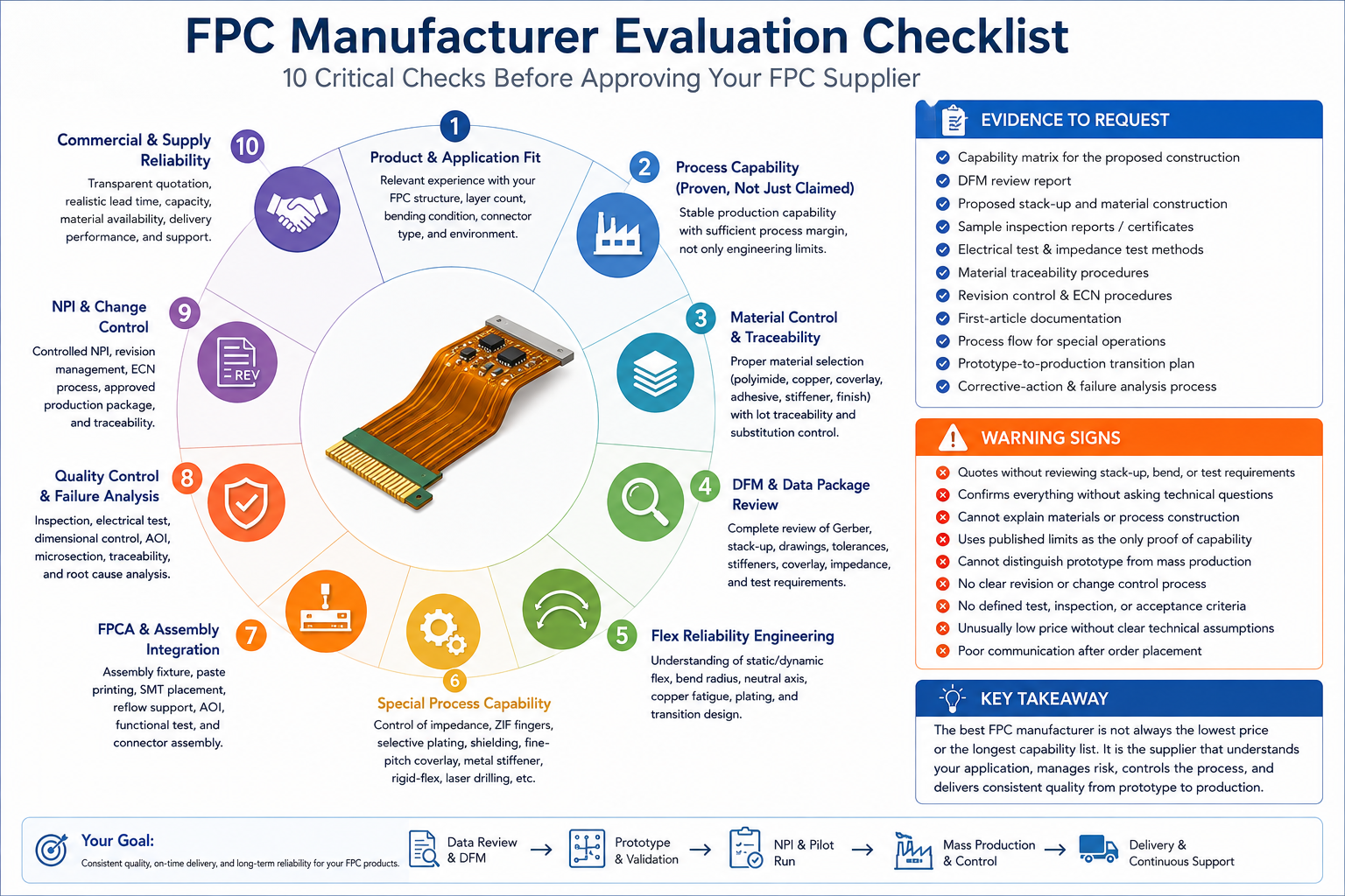
This guide outlines ten practical areas that engineering teams and purchasing professionals should review before approving an FPC supplier for prototype, NPI, pilot-run, or production orders.
1. Is the Manufacturer Experienced With Your Specific FPC Structure?
The first qualification question is whether the manufacturer has produced circuits with a construction and operating condition comparable to your project. General experience with flexible circuits is useful, but product-specific experience is more important.
Relevant structural experience may include:
- Single-sided, double-sided, or multilayer FPC constructions
- Adhesive-based or adhesiveless flexible laminates
- Static-flex, installation-flex, or dynamic-flex applications
- ZIF contact fingers and controlled insertion thickness
- Fine-pitch coverlay openings and dense SMT areas
- Controlled-impedance flexible circuits
- EMI-shielded FPC constructions
- Rigid-flex PCB structures and flex-to-rigid transition areas
- Flexible PCB assembly and completed FPCA products
A supplier should not be approved solely because it claims to manufacture “multilayer FPC.” The technical review should confirm the actual layer count, dielectric system, copper construction, via structure, finished thickness, bending condition, dimensional tolerance, and connector requirements that the supplier has previously controlled.
For example, a four-layer static-flex circuit installed once inside an enclosure is not equivalent to a four-layer circuit subjected to repeated motion. Both may have the same nominal layer count, but the copper selection, stack-up balance, bend-zone routing, plating distribution, coverlay design, and reliability expectations are different.
Customers should provide the proposed stack-up, fabrication drawing, bend information, connector details, and application conditions during supplier evaluation. The manufacturer’s technical response will often reveal whether it understands the product or is only reviewing the artwork at a superficial level.
FPCFAB reviews structure, materials, mechanical conditions, and production requirements as part of its flexible PCB manufacturing support.
2. Are the Published Capabilities Supported by Stable Production Processes?
Supplier websites often list minimum line width, minimum spacing, minimum via diameter, maximum layer count, and tight dimensional tolerances. These figures should be treated as declared limits, not automatic evidence of stable production capability.
A capability achieved on one engineering sample may not provide sufficient process margin for repeat production. Supplier qualification should distinguish between:
- Engineering limit
- Prototype capability
- Standard production capability
- Capability requiring special process control
This distinction is especially important when the design combines several difficult features. Fine conductor geometry may be manageable with thin copper, but the same line width can become significantly more difficult when combined with heavy copper, tight coverlay registration, small annular rings, selective hard-gold plating, or a thin finished construction.
Ask the supplier how it controls the proposed features under production conditions. A technically credible response should address process sequence, registration allowance, etching compensation, plating buildup, lamination movement, inspection method, and expected yield.
Process capability should also be evaluated against the complete design rather than isolated dimensions. A circuit may meet the stated minimum line width and minimum spacing while still presenting unacceptable risk because of local copper density, stiffener alignment, coverlay web width, panel distortion, or final outline tolerance.
A manufacturer with practical experience will normally identify where the design operates comfortably within its production window and where additional review, tooling, or customer approval is required.
3. How Does the Supplier Control Materials and Traceability?
Material selection is a major part of FPC performance. Polyimide thickness, copper foil type, adhesive system, coverlay construction, shielding material, stiffener material, and surface finish all influence mechanical behavior, electrical performance, assembly compatibility, and long-term reliability.
The supplier should be able to explain and control the following:
- Polyimide base-film thickness
- Adhesive-based or adhesiveless copper-clad laminate
- Rolled annealed copper or electrodeposited copper
- Base copper and finished copper thickness
- Coverlay film and adhesive thickness
- Bondply or bonding-film construction
- FR4, polyimide, stainless steel, or aluminum stiffeners
- Pressure-sensitive adhesive
- Conductive shielding film or copper shielding
- Surface-finish materials and plating thickness
Material qualification should not be reduced to a generic description such as “polyimide material.” The approved production package should identify the required material type, construction, thickness, and any customer-controlled brand or equivalent-material restrictions.
Traceability requirements should be proportional to the application. For normal commercial projects, basic lot identification and material records may be sufficient. Automotive, medical, aerospace, industrial, or other controlled applications may require more extensive material certification, lot traceability, retained records, and approval before substitution.
Material substitution is a common supplier-management risk. A responsible manufacturer should not change the laminate, coverlay, adhesive, stiffener, shielding film, or surface-finish process without documented technical review and customer approval when the material is controlled by the drawing or purchase specification.
The supplier should also identify material availability, supplier minimum order quantities, shelf-life restrictions, and long-lead items during quotation. These factors affect both project cost and delivery stability.
4. Can the Supplier Perform a Complete DFM and Data-Package Review?
FPC manufacturability cannot be confirmed from copper Gerber files alone. The manufacturer should review the complete technical data package and resolve conflicts before tooling or production release.
A complete FPC data package may include:
- Gerber, ODB++, or IPC-2581 production data
- NC drill and route files
- Fabrication drawing
- Layer stack-up
- Material and copper-thickness requirements
- Coverlay construction and opening information
- Stiffener location, material, thickness, and tolerance
- Surface finish and contact-finger requirements
- Controlled-impedance values and reference layers
- Bend radius, bend direction, and flex-cycle information
- Electrical test and inspection requirements
- Panelization or assembly-carrier requirements
- BOM, centroid data, and assembly drawings when FPCA is required
A proper DFM review should identify missing information, conflicting dimensions, unrealistic tolerances, weak copper transitions, insufficient coverlay clearance, unsuitable via placement, stiffener interference, panelization risk, and assembly constraints.
The supplier should not resolve unclear requirements by making undocumented assumptions. Examples requiring clarification include different finished-thickness values on separate drawings, undefined hard-gold thickness, missing bend-cycle requirements, inconsistent drill data, or a stiffener drawing that conflicts with the Gerber outline.
DFM feedback should distinguish between mandatory changes and recommendations. Mandatory changes are required for process feasibility or reliability. Recommendations may improve yield, reduce cost, increase mechanical margin, or simplify assembly without being essential to production.
FPCFAB provides FPC design and DFM review for stack-up, routing, bend zones, coverlay, stiffeners, tolerances, connector areas, and assembly-related risks.
5. Does the Manufacturer Understand Flex Reliability Engineering?
Mechanical reliability is a defining characteristic of an FPC. A supplier should understand how copper, dielectric layers, adhesive, coverlay, plating, shielding, and stiffeners behave as one structure during bending.
The engineering review should establish whether the application involves:
- Static installation bending
- Repeated dynamic flexing
- A controlled fold during product assembly
- Twisting, rolling, or multidirectional movement
- Vibration or mechanical shock
- Elevated or low operating temperatures
Important reliability factors include bend radius, finished thickness, copper foil type, plated copper buildup, conductor orientation, trace geometry, material symmetry, neutral-axis position, coverlay transitions, stiffener edges, and the location of vias or solder joints.
Dynamic-flex regions should generally avoid vias, plated holes, abrupt trace-width changes, sharp copper corners, component pads, and stiffener terminations. The exact design rules depend on the stack-up, copper construction, bend direction, bend radius, and expected cycle life.
A technically competent manufacturer should also understand that simply specifying rolled annealed copper does not guarantee dynamic reliability. Copper thickness, grain orientation, plating distribution, local reinforcement, conductor routing, and total construction thickness remain important.
When reliability risk is significant, the supplier should request application details and recommend prototype evaluation or mechanical testing rather than relying only on nominal design rules.
Additional engineering considerations are covered in our FPC Design Guidelines.
6. Can the Supplier Control Special FPC Processes?
Many FPC projects include process requirements that are more demanding than standard copper imaging and coverlay lamination. Supplier qualification should confirm whether these processes are controlled internally, outsourced, or dependent on special tooling.
Examples include:
- Fine-pitch coverlay openings
- Photoimageable coverlay
- Laser-drilled microvias
- Controlled-impedance routing
- Crosshatched reference planes
- Conductive shielding-film lamination
- Selective EMI shielding
- Hard-gold ZIF contact fingers
- Selective surface finishes
- Metal stiffener bonding
- Pressure-sensitive adhesive application
- Rigid-flex lamination and transition control
For ZIF connector areas, the supplier should control contact pitch, exposed length, surface finish, hard-gold thickness where specified, stiffener position, and total insertion thickness. These requirements cannot be verified from the copper pattern alone.
For controlled-impedance FPCs, the manufacturer should review conductor geometry, dielectric thickness, dielectric properties, copper thickness, coverlay, reference-plane construction, and test-coupon requirements. Copying a trace width from a rigid PCB stack-up is not an acceptable impedance-control method.
For EMI shielding, the technical review should address shielding-film type, grounding method, shield termination, opening areas, local stiffness, bend performance, and assembly temperature exposure.
Rigid-flex projects require additional control of material compatibility, lamination sequence, rigid-to-flex transition geometry, coverlay termination, plated-hole reliability, and dimensional movement. Relevant support is available through our Rigid-Flex PCB Manufacturing service.
7. Can the Manufacturer Integrate FPC Fabrication and FPCA Requirements?
When components are mounted on the flexible circuit, fabrication and assembly should not be treated as unrelated processes. Thin FPC materials require controlled support during solder paste printing, component placement, reflow, inspection, handling, and testing.
FPCA capability should include practical control of:
- Assembly-panel or carrier-fixture design
- FPC flatness and positioning
- Solder paste printing on flexible substrates
- Fine-pitch SMT placement
- Reflow support and thermal exposure
- Manual soldering and connector installation
- AOI and visual inspection
- Electrical or functional testing
- Protection of flexible tails and contact fingers
- Packaging and handling after assembly
Component placement should avoid active bend areas unless the product structure provides controlled reinforcement. Heavy components, connectors, solder joints, and stiffener edges can create local stress concentration if the mechanical design is not reviewed as a complete assembly.
The supplier should also review fiducials, tooling holes, panel borders, breakout methods, component orientation, rework access, test-point locations, and the relationship between the FPC outline and the assembly fixture.
A single supplier responsible for both bare FPC and assembly can reduce interface risk, but only when the supplier has credible capability in both processes. Customers should evaluate fabrication and assembly controls separately rather than assuming that one capability automatically proves the other.
FPCFAB supports flexible PCB assembly / FPCA for prototype and production projects.
8. Are Quality Control, Testing, and Failure Analysis Adequate?
Quality-system certificates alone do not demonstrate product-specific control. Supplier qualification should examine how the manufacturer controls the actual processes and characteristics that affect the FPC.
For industry qualification and performance requirements applicable to flexible and rigid-flex printed boards, refer to IPC-6013E.
Typical inspection and test controls may include:
- Incoming material inspection
- Artwork and CAM verification
- Automated optical inspection
- Electrical continuity and isolation testing
- Dimensional inspection
- Finished-thickness measurement
- Surface-finish and plating verification
- Microsection analysis where required
- Controlled-impedance testing
- Visual inspection of coverlay, stiffeners, adhesive, and connector areas
- First-article inspection
- Final release and lot traceability
The inspection plan should reflect product risk. A simple single-net FPC does not require the same controls as a multilayer impedance-controlled circuit with hard-gold fingers, shielding, several stiffeners, and tight connector tolerances.
Customers should also ask how the supplier responds when defects occur. A useful corrective-action process should identify the failure mode, contain affected material, determine the root cause, implement corrective action, verify effectiveness, and prevent use of obsolete or uncontrolled production data.
Failure analysis capability is particularly important for intermittent opens, conductor cracking, plating defects, coverlay delamination, stiffener separation, dimensional instability, solderability concerns, or field failures associated with repeated flexing.
Required reports, certificates, retained samples, traceability periods, and customer-specific formats should be defined during quotation rather than after production has started.
9. How Are NPI, Revisions, and Engineering Changes Controlled?
A capable FPC supplier should support the complete product-development cycle from engineering samples to stable production. Prototype success alone does not prove that the design, material, tooling, and inspection controls are ready for repeat manufacturing.
The NPI process should establish:
- Approved customer data
- Approved stack-up and materials
- Manufacturing process flow
- Tooling and panelization
- Critical dimensions and acceptance criteria
- Electrical test requirements
- First-article or pilot-run results
- Open engineering issues
- Current revision status
Revision control is essential when the project contains multiple Gerber packages, drawings, stack-ups, BOM revisions, or customer engineering changes. The supplier should have a defined process for reviewing, approving, implementing, and recording each revision.
Engineering changes should identify the affected part number, previous revision, new revision, reason for change, affected tooling, material impact, work-in-process status, inventory disposition, and implementation date.
When the design moves from prototype to pilot production, the supplier should review whether prototype tooling, material assumptions, electrical testing, panel layout, and inspection methods remain suitable for volume production.
A supplier that manages revisions informally through isolated email attachments creates unnecessary risk. The approved manufacturing package should always identify the current production revision.
10. Is the Supplier Commercially and Operationally Reliable?
Technical capability is necessary, but long-term supply performance also depends on quotation accuracy, communication, capacity planning, material availability, lead-time control, and delivery discipline.
A complete quotation should state the main commercial assumptions, including:
- Material construction
- Finished copper and overall thickness
- Surface finish
- Stiffeners and pressure-sensitive adhesive
- Electrical test
- Controlled-impedance testing
- Tooling and NRE charges
- Prototype and production quantities
- Lead time
- Quality documentation
- Packaging and delivery terms
Unusually low quotations should be reviewed carefully. A lower price may be based on different material assumptions, omitted tooling, limited inspection, relaxed tolerances, unconfirmed plating requirements, or no allowance for required documentation.
The supplier should be able to explain the major cost drivers and recommend practical cost reductions without weakening required reliability. Examples include improving panel utilization, simplifying coverlay openings, using standard material thicknesses, separating critical and non-critical tolerances, or selecting the correct surface finish for the actual interface.
Price should be evaluated together with yield, engineering response, revision accuracy, delivery performance, and field risk. The lowest initial unit price is not always the lowest total acquisition cost.
For a detailed review of quotation variables, read What Affects FPC Cost?
How to Choose an FPC Manufacturer: Evidence to Request
Supplier evaluation becomes more reliable when capability claims are supported by project-relevant evidence. Depending on confidentiality and application requirements, useful evidence may include:
- A completed capability matrix for the proposed construction
- A preliminary DFM review of the actual customer data
- Proposed stack-up and material construction
- Sample inspection reports or certificates
- Electrical test and impedance-test methods
- Material traceability procedures
- Revision-control and ECN procedures
- Example first-article documentation
- Process flow for special operations
- Prototype-to-production transition plan
- Corrective-action and failure-analysis process
The objective is not to collect documents for their own sake. The evidence should demonstrate that the supplier understands the product, has an appropriate production method, and can maintain control after the initial prototype build.
FPC Manufacturer Qualification Checklist
| Qualification Area | What to Verify | Typical Evidence |
|---|---|---|
| Product fit | Experience with the required layer count, bend condition, connector structure, shielding, impedance, and application environment | Relevant process examples, technical review, proposed stack-up |
| Process capability | Stable production capability rather than an isolated engineering limit | Capability matrix, tolerance review, process explanation |
| Material control | Approved laminate, copper, coverlay, adhesive, stiffener, shielding, and finish | Material specification, traceability procedure, substitution control |
| DFM and CAM | Complete review of production data, drawings, stack-up, tolerances, and mechanical requirements | DFM report, clarification list, approved manufacturing package |
| Flex reliability | Understanding of static flex, dynamic flex, bend radius, copper fatigue, neutral axis, and transition design | Engineering recommendations, prototype plan, reliability review |
| Special processes | Control of impedance, shielding, ZIF fingers, fine-pitch coverlay, stiffeners, and rigid-flex requirements | Process flow, tooling plan, test method |
| FPCA integration | Support for fixtures, printing, placement, reflow, inspection, and functional testing | Assembly plan, carrier design, inspection method |
| Quality control | Incoming, in-process, electrical, dimensional, and final inspection | Control plan, inspection report, test record |
| Change control | Controlled NPI, revision management, ECN implementation, and traceability | Revision procedure, approved data package, change record |
| Supply reliability | Transparent quotation, realistic lead time, capacity, material availability, and delivery control | Quotation assumptions, schedule, supply plan |
Warning Signs During Supplier Evaluation
Further investigation is recommended when a supplier:
- Quotes without reviewing the stack-up, stiffeners, bend conditions, or testing requirements
- Confirms every requirement without identifying technical questions
- Cannot explain the proposed laminate, copper, coverlay, or shielding construction
- Uses published minimum capabilities as the only evidence of process control
- Does not distinguish prototype capability from repeat production capability
- Cannot define the approved production revision
- Has no clear process for material substitution or engineering changes
- Cannot describe electrical test, inspection, or acceptance criteria
- Provides an unusually low quotation without clear technical assumptions
- Offers limited engineering communication after receiving the order
A warning sign does not automatically disqualify a supplier. However, unresolved technical ambiguity before production frequently becomes a quality, delivery, or commercial problem later.
How FPCFAB Supports Supplier Qualification and Production
FPCFAB supports flexible circuit projects from initial technical review through prototype, NPI, pilot-run, and production stages. Project evaluation can include production data, stack-up, materials, copper construction, bend requirements, coverlay openings, stiffeners, connector areas, controlled impedance, shielding, dimensional tolerances, electrical testing, and assembly information.
Our service scope includes flexible PCB manufacturing, flexible PCB assembly / FPCA, FPC design and DFM review, and rigid-flex PCB manufacturing.
Customers may submit complete production files or preliminary design information. When critical requirements are missing or inconsistent, the open technical items should be resolved before quotation confirmation, tooling, or production release.
For a complete list of quotation inputs, see How to Prepare an FPC RFQ.
Conclusion
Knowing how to choose an FPC manufacturer requires a structured review of product fit, proven process capability, material control, DFM quality, flex reliability, special-process experience, FPCA integration, inspection, change control, and supply performance.
The most suitable supplier is not necessarily the manufacturer with the broadest advertised capability or the lowest quotation. It is the supplier that understands the actual application, identifies technical risk clearly, controls the approved production package, and delivers consistent products through prototype and production stages.
Provide candidate suppliers with the complete available project data and evaluate the quality of their technical response. Clear documentation and disciplined supplier qualification reduce quotation revisions, engineering delays, uncontrolled assumptions, production variation, and field reliability risk.
Send your Gerber files, fabrication drawing, stack-up, bend requirements, stiffener information, quantities, and assembly data to FPCFAB for engineering review and quotation support.