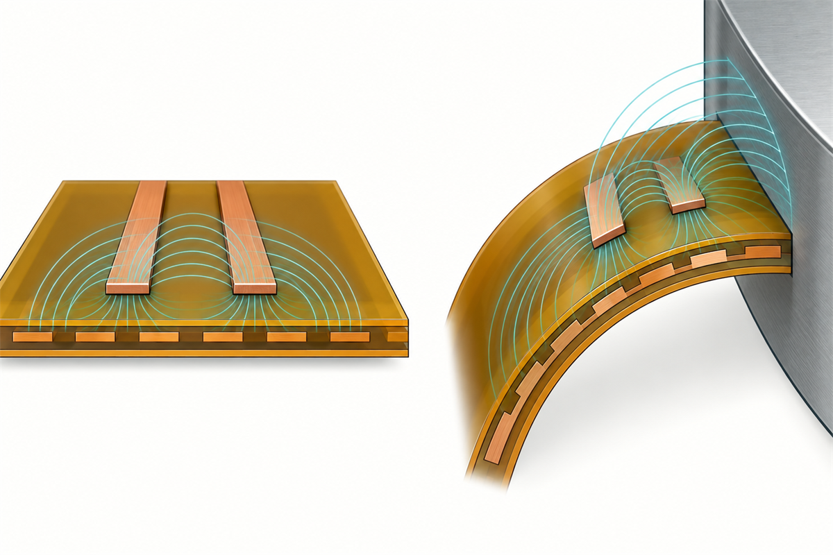
FPC impedance during bending is not governed by bend count alone. A bend can alter the electromagnetic environment if the transmission-line geometry, reference structure, pair symmetry, shielding, or proximity to nearby metal changes. Repeated flexing is a separate durability question: electrical behavior may change if cycling permanently deforms or damages the circuit, but there is no universal rule that every bend makes impedance increase.
1. Why FPC Impedance Can Change When the Circuit Bends
Characteristic impedance belongs to a transmission-line structure, not to a copper trace in isolation. Trace width and thickness matter, but so do the dielectric between the signal and its reference, the shape and continuity of that reference, differential-pair spacing, and the surrounding conductive environment. The broader controlled-impedance FPC design guide covers those flat-stack design inputs. The bend-specific question is whether they remain electrically equivalent in the installed shape.
A gentle bend in a uniform flex region may preserve the local cross-section well enough that the effect is small. A tighter or compound bend can introduce more meaningful differences: the inner and outer arcs experience different strain, a pair can lose symmetry, a hatched reference can deform relative to the traces, or a folded section can move close to another conductor, shield, chassis wall, or itself. These are geometry and coupling changes, so the direction and magnitude cannot be inferred from “bent” alone.
2. Separate Bent-State Change From Flex-Cycle Damage
Bent-state behavior
This is the electrical response while an intact circuit is held in a defined shape. A difference from the flat state may be reversible when the geometry returns, especially when it is caused by proximity, overlap, or coupling rather than damage.
Cycle-induced change
This is a persistent or intermittent change after repeated motion. It may involve conductor fatigue, local necking, cracking, delamination, reference-structure damage, or another physical change. Its onset depends on the actual construction, motion, radius, environment, and test definition.
Do not collapse these mechanisms into one trend line. A circuit may show a measurable difference when bent but return to baseline when flattened. Another circuit may remain stable for the specified test and then develop a localized discontinuity. Increased DC resistance, intermittent continuity, return-loss degradation, and a shifted TDR feature are different observations; none should be used as a substitute for the others without a defined correlation.
The FPC bend radius guide explains the mechanical difference between static and dynamic applications. For impedance work, carry that use definition into the electrical test plan rather than applying an unsupported cycle count or bend-radius multiplier.
3. What the Neutral Axis Tells You—and What It Does Not
In an idealized bent stack, the neutral axis is the region where longitudinal bending strain is near zero. Layers farther from it experience more tensile or compressive strain. In a real FPC, copper distribution, adhesive layers, coverlay, shields, and unequal material properties can shift the effective mechanical response. This is why layer position and stack symmetry matter when reviewing a bend zone.
The neutral axis is a mechanical-strain concept, not an impedance equation. Placing a critical conductor nearer the low-strain region may reduce mechanical demand, but it does not guarantee constant impedance. Electrical behavior still depends on trace-to-reference geometry, pair balance, dielectric configuration, nearby conductive objects, and the complete three-dimensional shape.
Molex’s current FPC Sample Kit separates mechanical guidance for trace routing, stacked conductors, service loops, cross-hatched planes, and symmetrical layouts from electrical challenges such as controlled impedance, crosstalk, and return paths. That separation is useful: mechanical design choices inform reliability, while an electrical model or measurement evaluates the channel.
4. Which Bend-Related Geometry Changes Matter Electrically?
| Possible change in the bent assembly | Why it may matter | What to review |
|---|---|---|
| Local signal-to-reference spacing or dielectric shape changes | The electric-field distribution can differ from the nominal flat cross-section | Stack construction, bend radius, lamination integrity, and configured geometry |
| Differential traces no longer follow equivalent paths | Pair impedance, skew, or mode conversion may change | Pair symmetry through the bend and transitions into rigid or stiffened areas |
| Hatched or segmented reference geometry deforms | Reference coverage and current-return geometry may vary along the bend | Hatch orientation, trace position, fill geometry, and model assumptions |
| Folded regions overlap or approach another conductor | New broadside or edge coupling can appear in the final assembly | Minimum installed spacing across the full tolerance and motion envelope |
| Shield film or chassis moves closer to the signal region | Capacitive coupling and return-current distribution can change | Bonding, grounding, enclosure distance, and the actual assembled state |
| Cycling produces a local physical defect | A discontinuity can alter impedance, resistance, loss, or intermittency | Electrical location plus physical inspection and continuity evidence |
Reference-plane and shielding choices are often mechanical compromises as well as electrical ones. The FPC EMI shielding guide provides related grounding and coverage context, while the stack-up design guide helps define the construction that must be modeled or tested.
5. Static Bend, Flex-to-Install, and Dynamic Flex Need Different Validation
A static bend remains in one installed shape during normal operation. Flex-to-install sees limited forming during assembly and then stays substantially fixed. Dynamic flex moves repeatedly in service. These labels do not define universal radii or cycle lives, but they do determine which state must be evaluated.
For a static or flex-to-install interconnect, compare the flat design state with the final installed state, including enclosure and shield proximity. For a dynamic application, define the complete motion envelope: bend location, minimum and maximum configured radius, angle, travel, speed, dwell, temperature, and the points at which electrical measurements are required. Acceptance criteria should be agreed for the real channel, not inferred from a generic material claim.
6. Model the FPC in Its Final Bent Configuration
When coupling or three-dimensional proximity is important, compare the flat and configured states in an electromagnetic model. Ansys documents a rigid-flex workflow that can analyze flat and bent designs, and its HFSS material specifically notes that wrapping a flex cable in the assembled configuration helps account for coupling effects that a flat approximation may miss. This supports a principle, not a software mandate: use a model that represents the geometry relevant to the decision.
The model should include the signal and reference conductors, dielectric regions, shields, adjacent boards or metal, connector launches where relevant, and enough of the surrounding structure to capture the intended coupling. Material values and layer dimensions should come from the controlled stack-up and supplier-confirmed data. The goal is not to create a visually convincing bend; it is to compare electrically meaningful states under documented assumptions.
7. How to Test Whether Bending Changes Impedance
- Establish a flat-state baseline. Record the test setup, reference planes, launch or fixture, cable orientation, temperature, and the TDR or S-parameter result used for comparison.
- Define a repeatable bend fixture. Control the bend line, radius or forming surface, angle, installed spacing, and nearby conductive objects. Avoid hand-held positioning when small geometry differences could dominate the comparison.
- Measure the configured state. Where access permits, compare the intact circuit while held flat and bent. De-embedding, fixture characterization, bandwidth, and spatial resolution must be suitable for the feature being investigated.
- Run durability cycling separately when required. Use the project-defined motion and environment. Do not treat one supplier’s cycle result as a universal qualification level.
- Repeat electrical checks at defined intervals. Compare the same measurement states so that bend-position variation is not mistaken for accumulated damage.
- Correlate electrical and physical evidence. A localized TDR change can guide inspection, but confirmation may also require resistance/continuity data, microscopy, cross-sectioning, or another agreed method.
IPC’s public test-method index identifies IPC-TM-650 2.5.5.7A for characteristic-impedance measurement by TDR and IPC-TM-650 2.4.3F for flexural endurance of flexible printed board materials. Their roles should remain distinct: an impedance method does not define product fatigue life, and a material flexural-endurance method is not automatically an assembled-product dynamic-flex qualification.
8. How to Interpret a Change After Flex Cycling
| Observation | Reasonable interpretation | Next check |
|---|---|---|
| Flat and bent results are stable and repeatable | No significant change was resolved under the defined setup | Confirm the setup covers the required installed and motion states |
| A feature appears only while the intact circuit is bent | Configured geometry or coupling may be involved | Vary the controlled bend state and compare with the 3D model |
| A localized feature remains after the circuit is flattened | A permanent structural or launch change is possible | Locate the feature, check resistance/continuity, and inspect the corresponding region |
| DC resistance rises or becomes intermittent | Conductor or interconnect damage may be developing | Use a suitable four-wire or continuity method and correlate with physical evidence |
| Broad insertion-loss or return-loss degradation occurs | Loss, reference, shielding, fixture, or multiple discontinuities may contribute | Recheck calibration and fixture repeatability before assigning a failure mechanism |
These are diagnostic clues, not automatic root-cause verdicts. The same electrical symptom can have more than one physical cause, and a real defect can affect resistance or loss before it creates an obvious visual crack.
9. FPC Bending and Impedance Documentation Checklist
- Identify whether the use is static, flex-to-install, or dynamic.
- Show the bend region, direction, installed geometry, motion envelope, and nearby conductive structures.
- Release the controlled signal/reference stack-up, material family, copper type, and relevant dimensional tolerances.
- Define the impedance target and tolerance at the correct reference plane; keep product limits separate from coupon limits.
- State whether acceptance is based on flat, configured, post-cycle, or multiple measurement states.
- Define the electrical method, fixture, bandwidth, de-embedding approach, sampling, and evidence format.
- Keep DC resistance, continuity, TDR, insertion/return loss, and physical inspection as distinct but correlatable evidence.
- Record customer and project-matched manufacturing partner approvals for construction-specific assumptions and limits.
Frequently Asked Questions
Can an FPC pass impedance testing flat but behave differently after installation?
Yes, if the installed shape introduces coupling or proximity that the flat coupon or flat product test does not reproduce. The practical importance depends on the channel bandwidth, geometry, and system margin.
Does placing a trace near the neutral axis guarantee constant impedance?
No. It can reduce mechanical strain demand in a defined construction, but impedance still depends on the complete electrical geometry and environment.
Should TDR be performed while the FPC is bent?
It can be useful when the engineering question concerns the configured state and a repeatable fixture is possible. It is not automatically required for every FPC, and the test plan must separate fixture effects from the product response.
Can repeated bending damage a differential pair before it becomes open-circuit?
Potentially. A developing structural change may alter resistance, balance, loss, intermittency, or a localized TDR response before a permanent open occurs. The actual sequence is construction- and application-specific.
Technical References
Current document roles and revision dates were checked against the Global Electronics Association’s status of standardization. Relevant measurement-method titles were checked against the official IPC-TM-650 test-method index. Bent-versus-flat modeling context was checked against Ansys’s rigid-flex bend analysis documentation and its HFSS 2022 R2 flex workflow overview. Mechanical and signal-integrity context was checked against Molex’s FPC Sample Kit technical guide. Manufacturer guidance supports the engineering workflow but is not a universal FPC limit.
Review the Installed Flex Geometry Before Release
FPCFAB can organize the stack-up, bend definition, impedance requirement, and validation evidence for DFM and quotation review with a project-matched manufacturing partner. Material selection, achievable construction, modeling scope, electrical test method, acceptance limits, cost, and schedule remain subject to confirmation for the actual project.