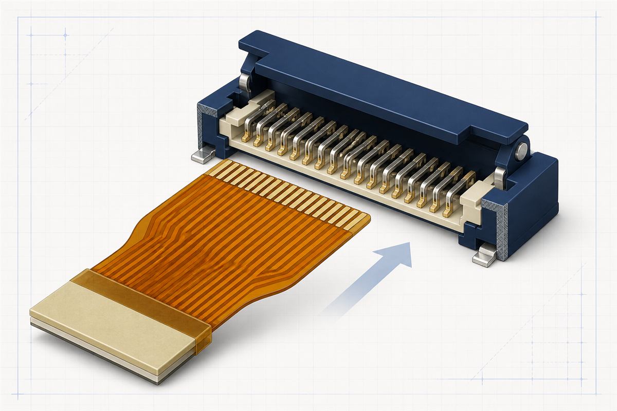
FPC ZIF connector design is an interface-control task, not simply a matter of matching contact pitch. A flex tail can have the correct pitch and pin count and still fail to mate because the contact side, finished tail thickness, exposed-finger length, stiffener construction, or datum scheme does not match the selected connector.
1. Start With the Full Connector Part Number
“0.5 mm pitch ZIF” is not a complete interface definition. Connector families with the same pitch can differ in circuit count, contact position, actuator style, insertion depth, recommended FPC outline, mating-thickness range, hold-down geometry, and allowed plating system.
The FPC fabrication drawing should identify the full connector part number and the drawing revision used for the design. If a second-source connector is required, its recommended FPC pattern must be checked separately. A part should not be called a drop-in alternative only because its board footprint and pitch look similar.
2. Confirm Contact Orientation Before Routing
ZIF and FPC connectors are commonly described as top-contact, bottom-contact, or dual-contact. This indicates where the connector terminals engage the exposed conductors on the inserted flex tail. The terminology must be checked against the selected manufacturer’s drawing because viewing direction and board orientation can cause avoidable confusion.
Single-Ended Tail
For a one-connector tail, confirm whether the exposed contact fingers face toward or away from the PCB after insertion. The installation drawing should show both the connector actuator and the FPC copper side.
Two-Ended Interconnect
For an FPC with connectors at both ends, define whether the exposed contacts are on the same side or opposite sides. “Type A” and “Type B” descriptions are not sufficiently universal for production data; show the layer orientation in the drawing.
A mirrored tail may fit mechanically but connect the circuits in the wrong order. Pin 1 identification, conductor-side orientation, insertion direction, and the assembly view should therefore appear together in the released documentation.
3. Control the Finished Mating Thickness
The connector engages the finished FPC tail, not the nominal stiffener sheet by itself. The mating thickness can include the flex base material, copper, coverlay or local dielectric construction, plating, stiffener, and bonding adhesive. Every layer that remains in the insertion zone contributes to the tolerance stack-up.
A useful drawing defines the finished thickness at the contact tail as a controlled dimension and separately identifies the stiffener material and nominal thickness. This avoids a common purchasing mistake: ordering a familiar stiffener thickness without checking whether the assembled tail fits the connector’s specified range.
The stiffener may be polyimide, FR-4, or another approved material depending on the connector interface and application. Material selection should follow the mechanical, thermal, and assembly requirements rather than a generic preference. See the FPC stiffener design guide for the construction issues outside the contact zone.
4. Use the Connector Drawing for Finger Geometry
The recommended FPC layout normally controls the tail width, contact pitch, conductor width, exposed-contact length, edge margins, insertion depth, and any required shoulder or datum feature. These dimensions work as a system. Changing one value independently can reduce lateral alignment margin or move the connector contact point too close to the end of the plated finger.
| Interface Feature | What Must Be Defined | Typical Failure if Uncontrolled |
|---|---|---|
| Pitch and conductor centerline | Pitch, conductor width, pattern position, and cumulative pattern tolerance. | Terminal-to-finger misregistration, especially at the outer circuits. |
| Tail width and edge datum | Finished outline width, reference edge, and relationship between outline and copper pattern. | Side loading, uneven engagement, or the tail not entering the guides. |
| Exposed-contact length | Coverlay opening, insertion depth, and connector wipe/contact zone. | Contact lands partly on coverlay or too close to the finger end. |
| Finger end geometry | End clearance, corner condition, and any specified bevel or lead-in. | Scraping, snagging, copper burr risk, or difficult insertion. |
| Pin 1 and circuit numbering | Clear pin-1 mark and numbering viewed from a defined side. | Mirrored net assignment or assembly error. |
For fine-pitch interfaces, cumulative registration across the full contact array matters as much as the width of an individual finger. The supplier’s DFM review should therefore assess copper-to-outline registration and coverlay-to-copper registration, not only the nominal CAD dimensions.
5. Keep Coverlay and Adhesive Out of the Contact Zone
The coverlay opening establishes where the contact fingers are exposed. Its edge should be positioned from the connector interface requirement, with allowance for coverlay registration and adhesive flow. A nominal opening that ends exactly at a connector contact point leaves no practical process margin.
Adhesive squeeze-out onto the plated fingers can increase contact resistance or interfere with insertion. The drawing should clearly identify the no-contamination area and should not rely on the finished appearance of a reference photograph. When a coverlay opening, stiffener edge, and tail outline terminate in the same region, their separate tolerances need to be reviewed together.
More construction details are covered in the FPC coverlay design guide.
6. Specify the Contact Finish for the Actual Mating System
The exposed fingers require a surface finish compatible with the connector terminal material, required contact resistance, assembly process, environmental exposure, and expected mating cycles. “Gold finish” is not a sufficient procurement description.
Electroless nickel immersion gold (ENIG) and electroplated nickel/gold are different processes with different deposit characteristics. A finish that is acceptable for a low-cycle connector may not be the correct choice for repeated insertion. The required nickel and gold system, thickness, coverage, and any selective-plating boundary should be agreed from the connector and product requirements.
Do not assume that a harder or thicker gold deposit is automatically better. Excess build-up changes the local thickness, while an unsuitable underlayer or process boundary can create other reliability concerns. Record the agreed finish in the fabrication drawing and purchase specification. For a broader comparison, refer to the FPC surface finish guide.
7. Design the Stiffener Transition, Not Only the Tail
The connector needs a sufficiently rigid insertion tail, but the flex must also survive immediately behind it. A sharp stiffness change can concentrate strain at the stiffener edge. This area deserves the same attention as the plated fingers.
- Keep dynamic bending away from the stiffener termination and the connector exit.
- Avoid vias, pads, neck-downs, and abrupt conductor-direction changes at the stiffness transition.
- Route conductors smoothly through the transition and maintain practical spacing from the trimmed edge.
- Where the application permits, use a gradual support or strain-relief concept instead of forcing a tight bend directly against the stiffener edge.
- Check the installed bend direction against the copper-layer arrangement and connector orientation.
The minimum bend radius cannot be selected from connector pitch alone. It depends on the FPC construction, copper type and thickness, layer count, bend angle, number of flex cycles, and local geometry. See the FPC bend radius guide for the correct design inputs.
8. Build a Real Tolerance Stack-Up
Connector interfaces fail at the limits, not at the nominal dimensions. The engineering review should compare the connector’s allowable mating range with the worst-case finished FPC condition.
Thickness Stack
Base film, copper, plating, dielectric or coverlay, stiffener, and adhesive bond line should be included where they are present in the mating zone. Supplier process capability must support the finished-tail requirement.
Positional Stack
Connector guide clearance, FPC outline tolerance, copper-to-outline registration, contact pitch accumulation, and coverlay registration jointly determine the usable contact overlap.
A worst-case check should cover more than whether the FPC can be inserted. It should also ask whether the connector terminals remain on the specified plated region, whether the actuator can close correctly, and whether the tail is retained without permanent deformation.
9. Define the Validation Plan Before Production
Dimensional inspection confirms that the FPC matches the released drawing, but interface reliability still requires validation in the intended connector and product assembly. The validation level should reflect the application risk and connector specification.
- Verify the exact connector part number and drawing revision used for the prototype.
- Inspect tail width, contact pattern, exposed-finger length, finished mating thickness, and stiffener position.
- Confirm conductor continuity and the pin assignment before mating.
- Inspect the contact area for contamination, plating defects, edge damage, and coverlay encroachment.
- Perform controlled sample insertion, actuator closure, retention, and removal checks.
- Evaluate contact resistance or electrical continuity in accordance with the connector and product validation plan.
- Check the installed bend, strain relief, clearance, and movement through the product’s expected operating condition.
Prototype approval should use production-intent connector hardware. A successful fit in a visually similar connector is not proof that the released interface is correct.
Common FPC-to-ZIF Failure Symptoms
| Observed Symptom | Likely Interface Checks |
|---|---|
| Intermittent open circuit after assembly | Contact-side orientation, tail seating depth, contact overlap, contamination, plating condition, actuator closure, and local flex strain. |
| High insertion force or tail will not enter | Finished mating thickness, tail width, burrs, stiffener position, edge geometry, and connector actuator position. |
| Outer circuits lose contact | Cumulative pitch error, copper-to-outline registration, lateral play, tail skew, and guide clearance. |
| Visible wear or scratching on fingers | Plating system, finger-edge condition, connector damage, insertion angle, repeated mating, and foreign material. |
| Cracking near the stiffener edge | Installed bend radius, stiffness transition, copper routing, local stress concentration, and dynamic movement. |
| FPC backs out after operation | Insertion depth, actuator lock, mating thickness, cable loading, vibration, and strain relief. |
Information to Include in an FPC ZIF Connector RFQ
A complete RFQ shortens the DFM cycle and reduces the risk of quoting the wrong interface. Include:
- connector manufacturer, series, full part number, datasheet, and drawing revision;
- contact pitch, circuit count, pin numbering, and top-, bottom-, or dual-contact arrangement;
- FPC fabrication data, dimensioned drawing, stack-up, and outline tolerances;
- required finished thickness at the connector tail;
- contact-finger geometry, exposed length, and insertion direction;
- surface-finish specification and mating-cycle or environmental requirement when applicable;
- stiffener material, thickness, location, and bonding requirement;
- coverlay opening and no-contamination area;
- static or dynamic flex condition and the installed bend geometry;
- prototype quantity, production forecast, and required validation records.
If some information is unavailable, mark it as unknown rather than filling the drawing with assumed values. The FPC RFQ requirements checklist covers the remaining fabrication information needed for review.
Frequently Asked Questions
Can I design the FPC from pitch and pin count alone?
No. The full connector part number is required because the mating thickness, contact side, insertion depth, tail outline, and recommended contact geometry vary between connector series.
Is the stiffener thickness the same as the mating thickness?
Not necessarily. Finished mating thickness includes the complete local construction present in the connector interface. The stiffener is only one part of that stack.
Should the FPC use ENIG or hard gold?
There is no universal answer. Select and specify the finish from the connector terminal system, contact-resistance requirement, environment, and expected mating cycles, then confirm manufacturability with the chosen supplier.
Can a top-contact connector replace a bottom-contact version?
Only if the complete electrical and mechanical design is changed or the alternative connector is explicitly validated. Otherwise, the FPC contacts may face away from the terminals.
Why does an FPC fit but still lose contact?
Mechanical entry does not confirm correct contact overlap. Check tail seating, finished thickness, lateral registration, actuator closure, plating condition, and cable loading.
Does IPC-2223 replace the connector drawing?
No. IPC-2223 provides flexible printed board design guidance. The connector manufacturer’s current product drawing controls the connector-specific mating interface.
Technical References
IPC identifies IPC-2223 as the sectional design standard for flexible printed boards. Connector-specific requirements should be taken from the exact manufacturer’s product data. Examples of official connector resources include the Hirose FH12 series catalog, TE Connectivity product data, and Omron’s FPC/FFC connector guide. These examples demonstrate why dimensions and contact configurations must be checked by part number rather than transferred between connector families.
Need an FPC Connector Interface Review?
Send the connector part number and current drawing together with your FPC data, required quantities, mating orientation, finished-tail thickness, and application conditions. FPCFAB can organize the available information and coordinate a preliminary DFM and manufacturing review with a suitable production partner. Final capability, tolerances, finish, cost, and lead time are confirmed only after the complete project data have been reviewed.
Request an FPC Quote View FPC Manufacturing Support