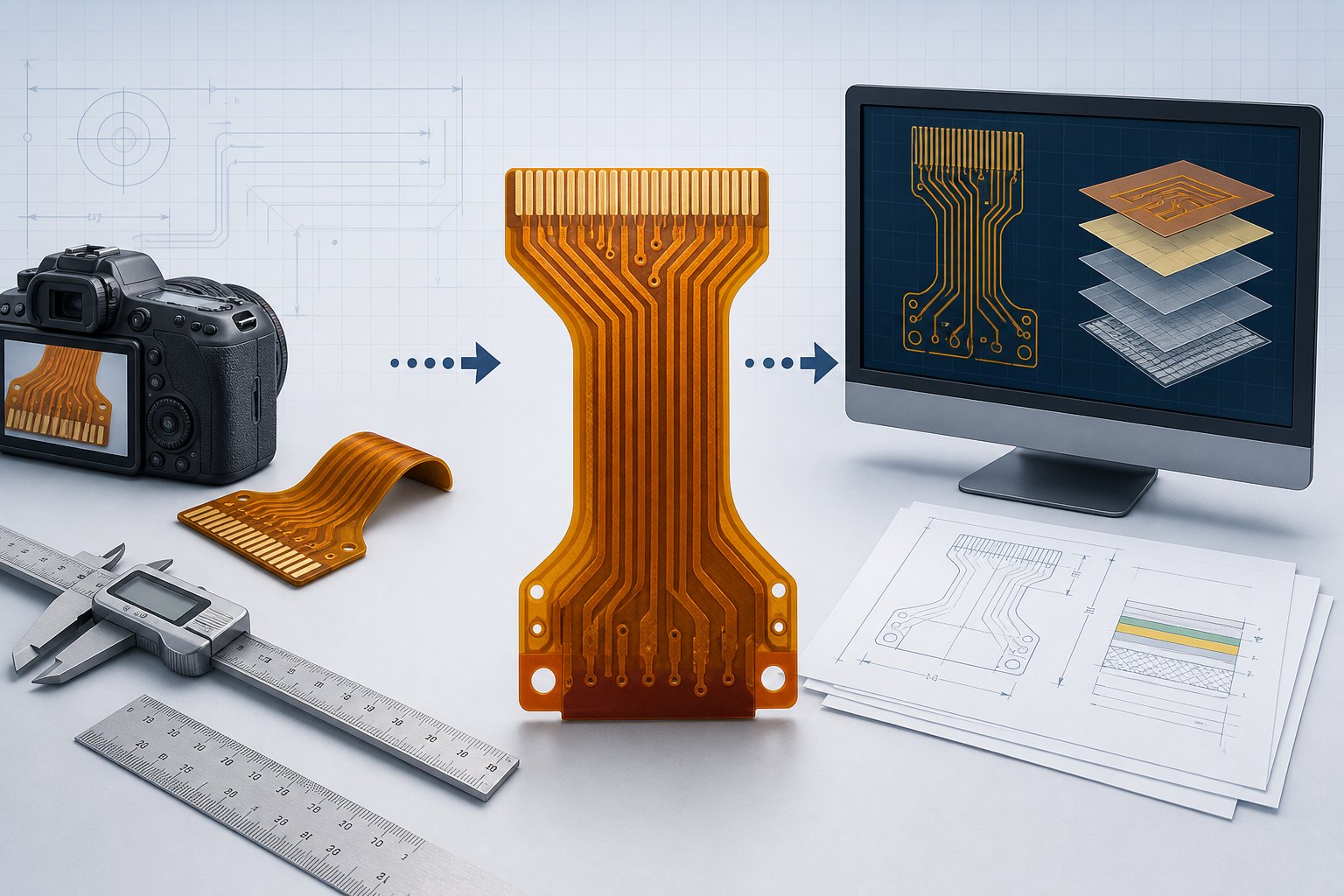
Can you reproduce FPC without Gerber files? In some cases, a missing Gerber package does not end an FPC replacement project. Photos, dimensions, a physical sample, and electrical information can support an initial engineering assessment. However, they do not automatically provide enough verified data to manufacture a reliable replacement.
Why Gerber Files Matter
Gerber is a standard format used to transfer PCB layer image data for fabrication. In a normal FPC project, the manufacturing package may also include drill data, a fabrication drawing, an outline, stack-up information, material requirements, finished thickness, surface finish, stiffener details, and testing instructions.
To reproduce FPC without Gerber files responsibly, the missing manufacturing and electrical information must be rebuilt from verified evidence rather than guessed from appearance.
A photograph records visible appearance. It does not carry the same controlled coordinates, layer definitions, apertures, drilling information, or revision data as a manufacturing file set. This is why an FPC that looks simple in a photo may still contain critical information that cannot be measured visually.
For a new design with complete data, see our FPC RFQ requirements guide. When files are missing, the first task is to identify what information can be recovered and what must be recreated or independently verified.
What Photos and Measurements Can Reveal
Visible Outline
Straight-on photographs with a scale reference can help document overall length, width, local neck-down areas, slots, mounting holes, and visible bend regions.
Contact and Connector Geometry
Close-up images may show pin count, approximate pitch, contact side, exposed-finger length, stiffener position, and the direction in which the FPC enters a mating connector.
Visible Trace Routing
On a simple exposed or translucent construction, some conductor paths may be visible. Visibility does not prove electrical connectivity, copper thickness, or the absence of hidden features.
Mechanical Installation
Images of the installed FPC can explain bend direction, available space, contact orientation, attachment points, and areas exposed to movement or mechanical stress.
What Photos Cannot Reliably Confirm
- Electrical connectivity: two traces may appear close or continuous while being isolated, connected through a via, or routed differently on another layer.
- Hidden layers and plated features: internal copper, through-hole connections, buried structures, and details under coverlay or stiffeners may not be visible.
- Material construction: polyimide thickness, adhesive system, copper type, base copper thickness, plating, and coverlay construction cannot be determined accurately from appearance alone.
- Finished thickness: the flexible area, contact area, and locally stiffened areas may have different thickness requirements.
- Controlled electrical requirements: impedance, current capacity, insulation, shielding, grounding, and signal-integrity needs require design or application data.
- Manufacturing tolerances: a photo does not define which dimensions are critical or what variation the mating product can accept.
- Revision status: an available sample may not match the latest approved product revision.
These gaps explain why an immediate price based only on photographs is usually unreliable. The reconstruction method and engineering workload must be understood first.
Four Common Starting Conditions
| Photos Only | Useful for early screening and identifying obvious geometry. Normally insufficient for a production-ready reconstruction because dimensions, connectivity, material, and tolerances remain unverified. |
|---|---|
| Photos and Exact Measurements | Better for rebuilding the mechanical outline and connector regions. Electrical mapping and material construction are still required. |
| Physical Sample Available | Allows direct dimensional inspection and, when appropriate, continuity mapping or other analysis. The permitted inspection method and acceptable risk to the sample must be agreed in advance. |
| Sample Plus Electrical Data | A sample combined with a verified pin map, schematic information, connector documentation, or known function provides a stronger basis for reconstruction and prototype validation. |
Minimum Information for an Initial FPC Assessment
If your goal is to reproduce FPC without Gerber files, send as much of the following information as possible. Missing items do not automatically stop the review, but they must be identified.
- High-resolution, straight-on photographs of both sides on a plain background.
- A ruler or known scale reference in the same plane as the FPC.
- Overall outline dimensions, hole and slot locations, and all connector-related dimensions.
- Pin count, contact pitch, contact side, insertion direction, and mating-connector part number if known.
- Measured thickness in the flexible area and at each stiffened contact area.
- A verified pin-to-pin continuity map or connection table whenever possible.
- Photos showing the installed position, bending direction, and surrounding mechanical constraints.
- Application description, voltage or current information when relevant, and whether the FPC bends once or repeatedly during operation.
- Required quantities for prototype and possible later production.
- Any drawing, label, part number, damaged sample, connector datasheet, or related product document.
Can One Original Sample Be Kept Intact?
Sometimes a project must begin with the only working sample available. In that situation, the customer should state clearly that the sample cannot be damaged. Non-destructive review may include visual inspection, precision measurement, and accessible continuity mapping, depending on the structure and available access.
The limitation is important: a non-destructive method may not reveal copper hidden below coverlay, stiffeners, adhesive, shielding, or internal layers. If critical information remains hidden, the result may be an incomplete reconstruction rather than a verified copy.
When Destructive Analysis May Be Considered
For multilayer or concealed constructions, exposing internal features may require removal of material, sectioning, or another physical analysis method. Such work can permanently damage or consume the sample. It should be considered only when:
- the customer owns the sample or has proper authorization;
- the sample is not required for continued operation;
- hidden information is essential to the required deliverable;
- the analysis method and risk are agreed before work starts; and
- the expected value of the recovered data justifies the engineering cost.
Where only one irreplaceable working sample exists, obtaining a second damaged or non-working unit may be safer than sacrificing the operational part.
How to Reproduce FPC Without Gerber Files: A Practical Workflow
Collect Available Evidence
Organize photos, measurements, samples, continuity data, connector information, product context, and required quantities.
Identify Missing Information
Separate confirmed facts from assumptions. Record uncertain dimensions, hidden connections, unknown materials, and incomplete requirements.
Choose the Engineering Scope
Decide whether the project needs documentation reconstruction, a new replacement design, sample analysis, or only a preliminary feasibility review.
Create and Review Data
Prepare the required manufacturing documents and compare them with the verified sample information. Resolve conflicts before tooling or component purchasing.
Build a Prototype
A prototype checks mechanical fit, contact alignment, connectivity, bending, assembly interaction, and application-specific function.
Validate Before Production
Production quantity should be considered only after the customer has approved the prototype and any remaining limitations are documented.
Why a Reliable Quote Cannot Be Based on a Photo
A photo does not define the final deliverables or the engineering effort. One project may require only a simple outline reconstruction; another may require connectivity mapping, connector identification, material review, multilayer analysis, drawing creation, prototype production, and application testing.
For this reason, a responsible quotation may separate:
- initial engineering or feasibility review;
- measurement and documentation work;
- electrical mapping or sample analysis;
- CAD, Gerber, drawing, or BOM reconstruction;
- tooling or production preparation;
- prototype manufacturing;
- testing or validation support; and
- shipping and sample-return requirements.
See what affects FPC cost for general manufacturing cost drivers. Reconstruction work should be evaluated separately from the unit price of the finished FPC.
Authorization and Product Ownership
FPC reconstruction should be limited to customer-owned products, authorized repair or replacement work, legacy-product recovery, or projects for which the customer has the necessary rights. A request to duplicate a branded commercial part does not itself prove authorization.
Before accepting a project, the service scope, intended use, ownership, and authorization should be confirmed. This protects the customer, engineering partner, and manufacturing partner while keeping the project focused on legitimate repair, maintenance, redesign, and documentation recovery.
Frequently Asked Questions
Can an FPC be copied from a clear photo?
A photo may support an initial assessment, especially for visible single-layer geometry, but it does not verify connectivity, materials, thickness, hidden features, or tolerances. Production should not proceed from the image alone.
Can you quote 1, 5, 10, and 20 pieces immediately?
Unit quantities can be reviewed, but engineering and reconstruction scope must be understood first. Engineering, tooling, prototype, production, and shipping costs may need to be quoted separately.
Is a damaged sample useful?
Yes, if critical regions remain measurable. Explain which parts are damaged and provide photos before shipping. Damage may limit electrical or mechanical verification.
What if there is no BOM?
A bare FPC may not require a component BOM, but an assembled FPCA normally needs component identification and an approved BOM. Photos alone are not a controlled sourcing document.
Can the original sample be returned?
Return requirements should be agreed before analysis. Non-destructive work may preserve the sample, while destructive analysis may make return in the original condition impossible.
Does a successful prototype guarantee every application?
No. Prototype approval should use the customer’s relevant mechanical, electrical, environmental, and functional checks. The validation plan depends on the product and intended use.
Technical References
For formal background, Ucamco maintains the official Gerber format resources, while IPC lists IPC-2223 as the sectional design standard for flexible printed boards. Project-specific manufacturing and validation requirements still need to be agreed with the selected engineering and production partners.
Need an Initial FPC Reconstruction Review?
Send the clearest photos, exact measurements, available samples, connector details, continuity information, and required quantities. FPCFAB can organize the available data and coordinate an initial feasibility review with a suitable engineering or manufacturing partner. Feasibility, engineering scope, cost, and schedule are confirmed only after the submitted information has been reviewed.
Request an FPC Quote View Reverse Engineering Support