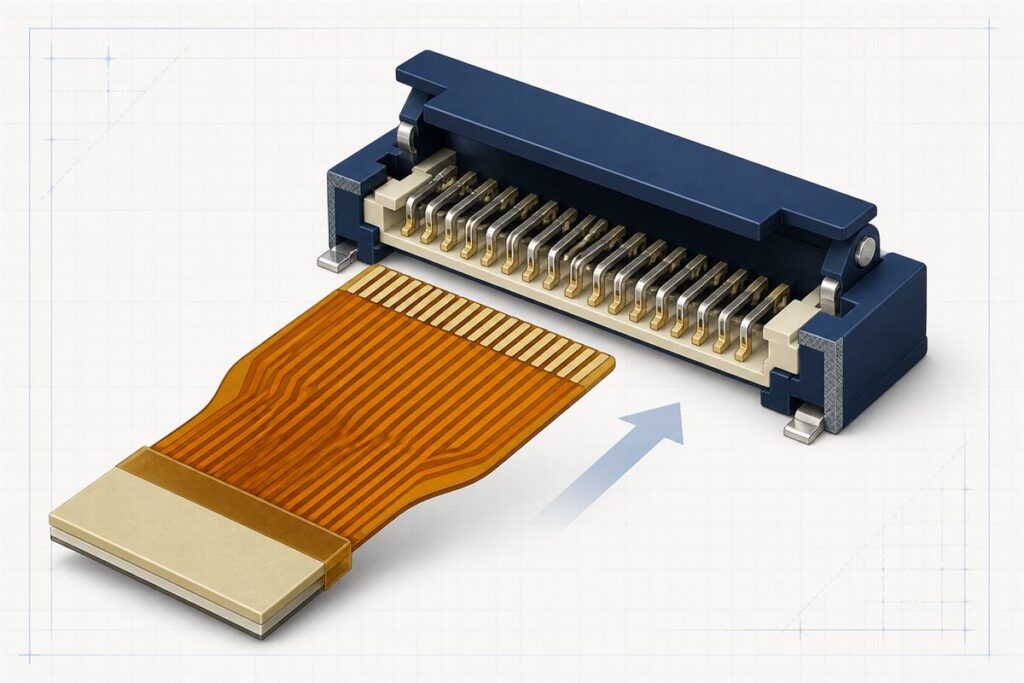
FPC ZIF Connector Design Guide: 9 Critical Requirements
A practical FPC ZIF connector design guide covering contact orientation, finger geometry, finished mating thickness, stiffeners, surface finish, tolerance stack-up, and prototype validation.

A practical FPC ZIF connector design guide covering contact orientation, finger geometry, finished mating thickness, stiffeners, surface finish, tolerance stack-up, and prototype validation.
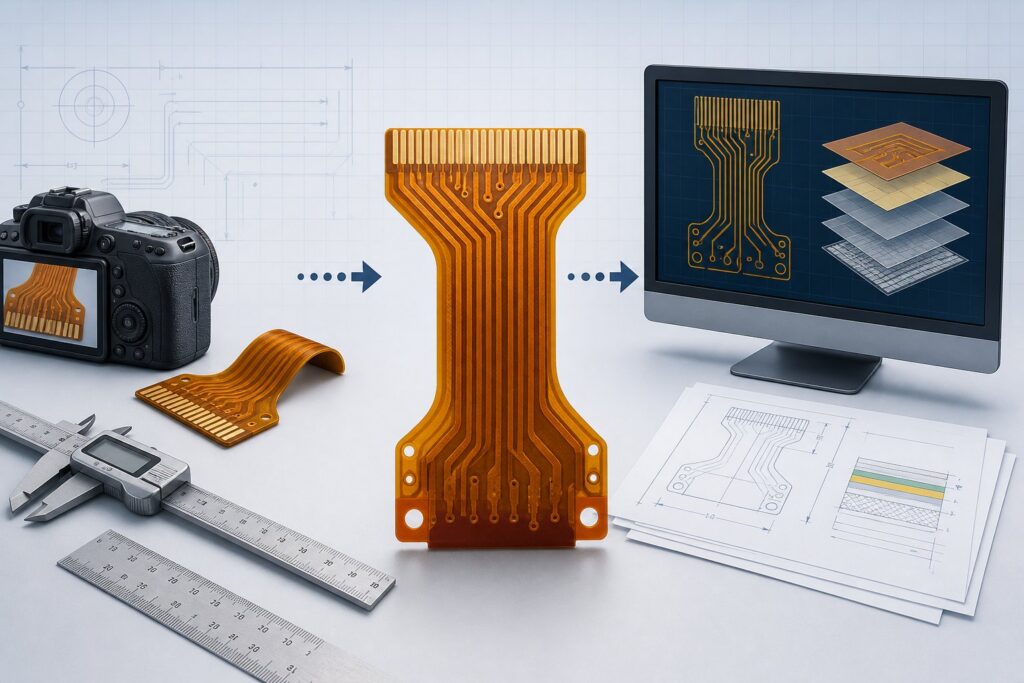
Can an FPC be reproduced without Gerber files? Learn what photos, measurements, samples, continuity data, and prototype validation are needed before manufacturing.
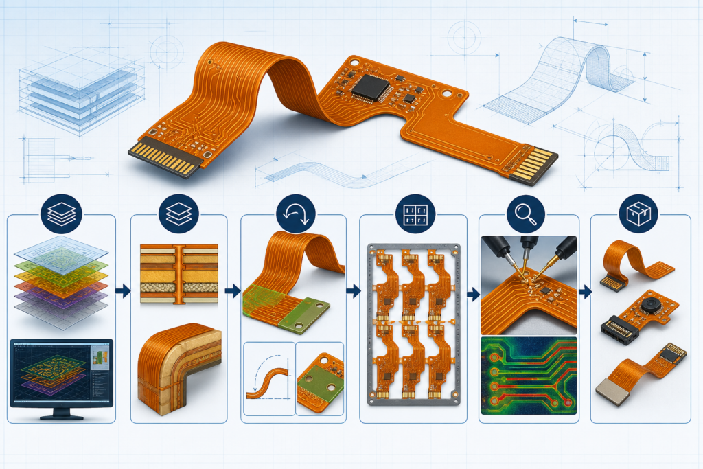
Plan an FPC prototype with a controlled data package, stack-up, DFM review, cost drivers, inspection, and validation checklist before production.
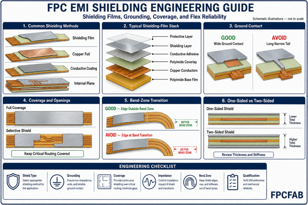
Learn how shielding-film selection, grounding, coverage, openings, stack-up, impedance, and bend-zone transitions affect FPC EMC performance and flex reliability.
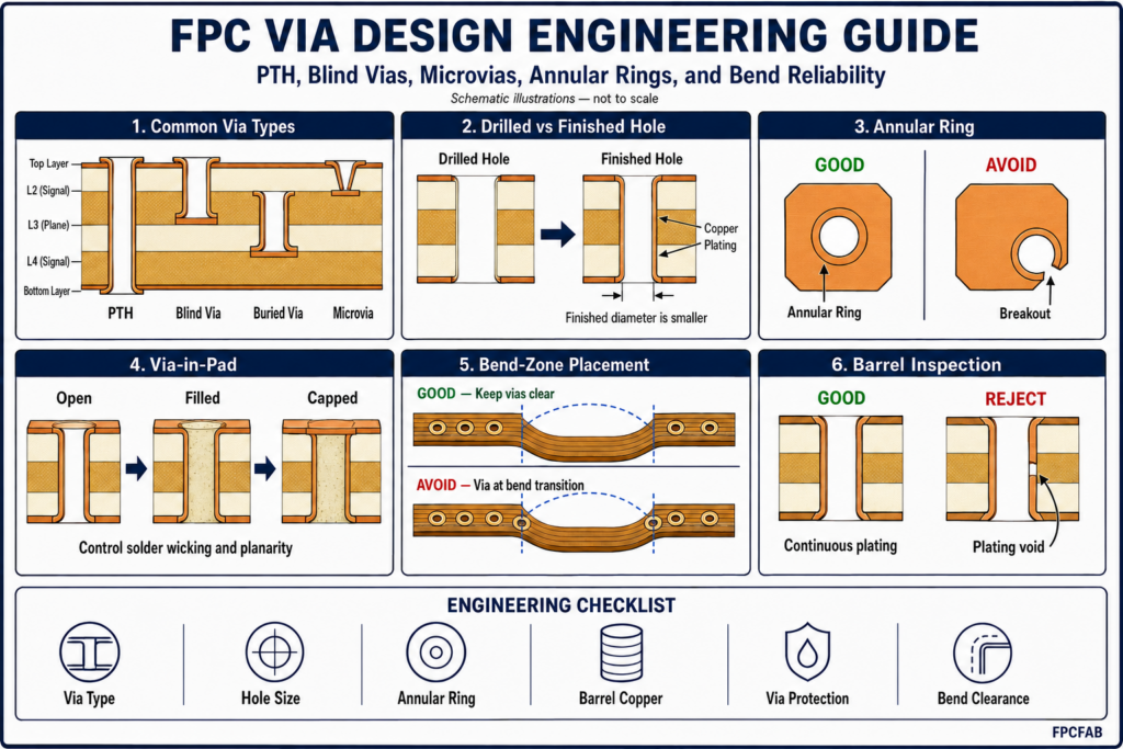
FPC via design must account for more than electrical layer-to-layer connection. Via type, drilled-hole size, finished-hole size, annular ring, copper
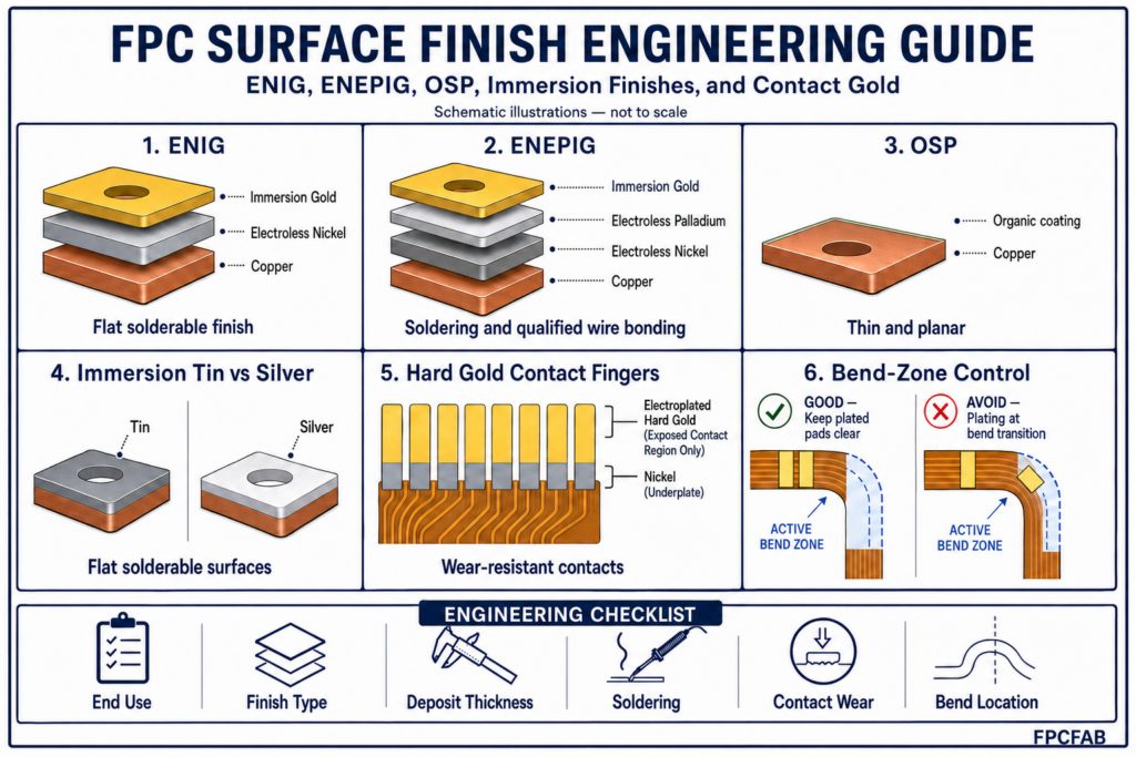
Learn how to select an FPC surface finish for soldering, wire bonding, contact fingers, storage, assembly, and long-term reliability.
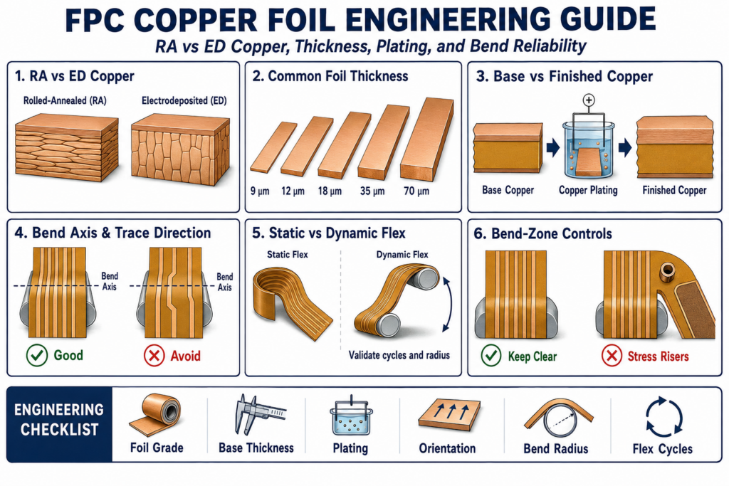
Learn how rolled-annealed and electrodeposited copper foil, copper thickness, grain structure, plating, bend orientation, and flex cycles influence FPC fabrication, electrical performance, and long-term reliability.
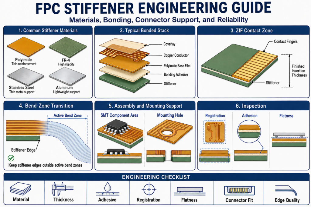
Learn how polyimide, FR-4, and metal stiffeners, adhesive systems, thickness, edge location, connector support, dimensional tolerance, and assembly loads affect FPC flatness and reliability.
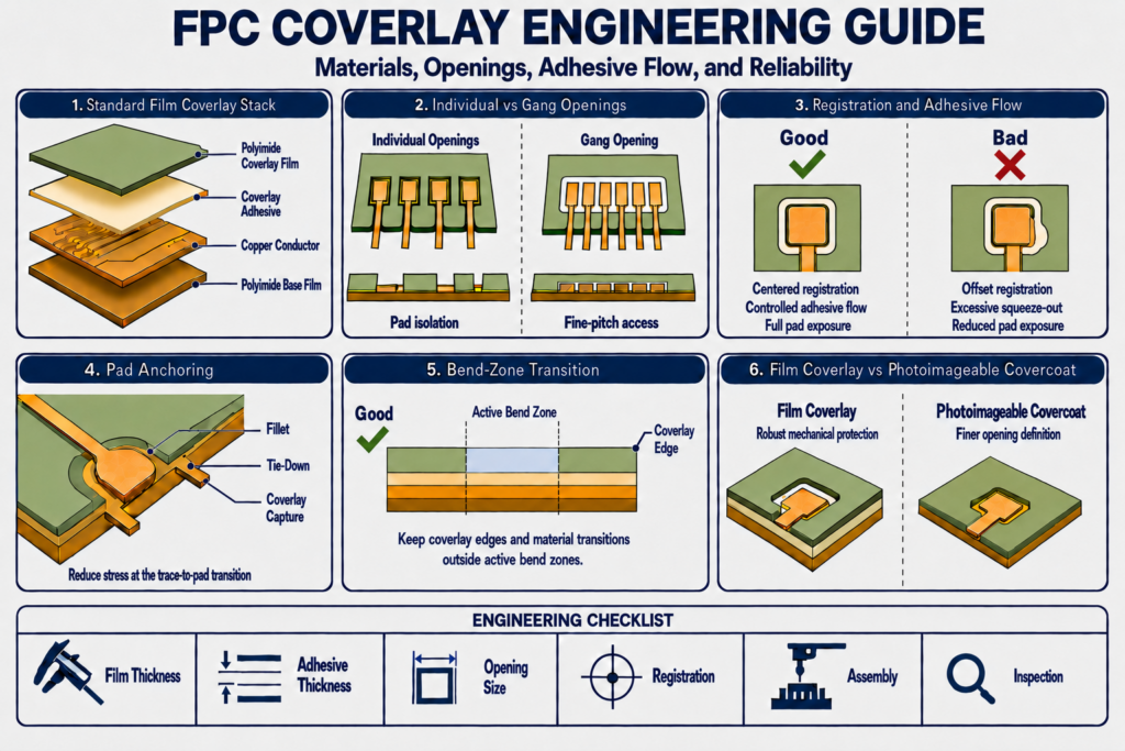
Learn how FPC coverlay film, adhesive thickness, opening geometry, registration tolerance, adhesive flow, and bend-zone transitions affect manufacturing, assembly, and long-term reliability.
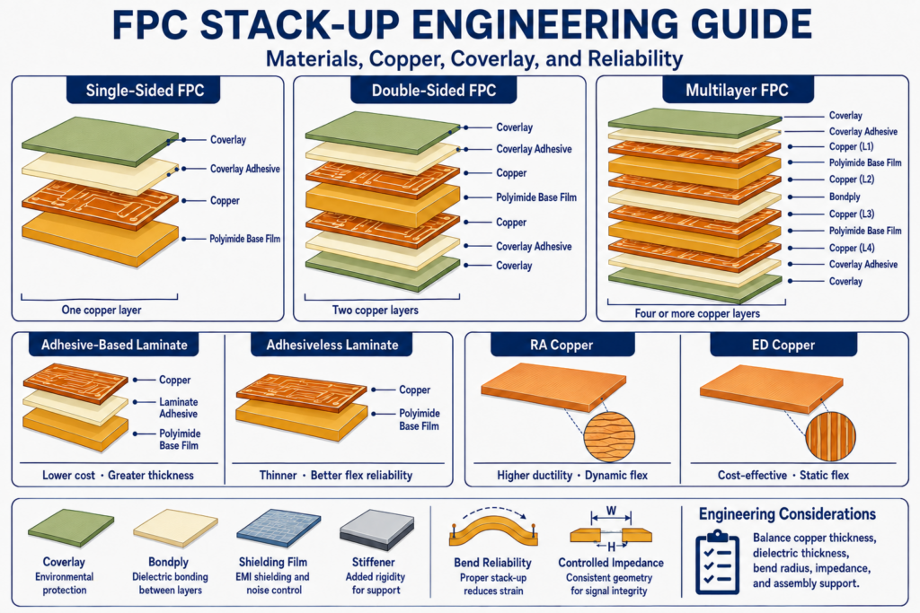
Learn how FPC stack-up design affects flexibility, finished thickness, copper reliability, coverlay, shielding, stiffeners, controlled impedance, assembly, and production yield.