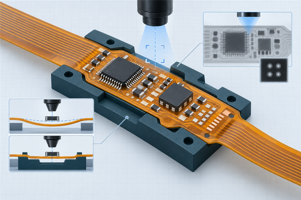
Fine-pitch FPC assembly is not simply ordinary SMT performed on a thinner board. Dense packages reduce the margin for printing, placement, inspection, and rework, while the flexible substrate makes local flatness and support part of the process definition. A useful DFM review therefore connects the package, land pattern, paste deposit, support condition, inspection evidence, and final product geometry before quotation or release.
1. What “Fine-Pitch FPC Assembly” Means Here
There is no single pitch or package size that makes every assembly “fine pitch” or “high density.” The engineering difficulty depends on the complete package and layout: lead geometry, termination visibility, exposed thermal pads, neighboring component clearance, land pattern, solder-mask definition, paste-release conditions, and access for inspection or rework. A component that is routine on one assembly can become higher risk when it is placed beside a connector, over a local thickness transition, or within a crowded supported region.
FPC fabrication density and assembly density are also different subjects. Fine traces, small vias, or a complex flex stack concern the bare circuit. Fine-pitch leads, bottom-terminated packages, dense component placement, and constrained rework access concern the assembled product. The two meet at the land pattern, coverlay or solder-mask openings, stiffener geometry, surface finish, and controlled fabrication data.
2. Why Flex Can Reduce Assembly-Process Margin
Local flatness can change
A thin flex region may follow the carrier, fixture, adhesive, vacuum surface, or nearby thickness transition. If the support condition changes between printing, placement, and inspection, the same nominal artwork can present a different physical surface to each process.
Support becomes part of the definition
The assembler must know which areas are temporarily supported, which permanent stiffeners remain in the product, where flex tails must stay free, and how the circuit is located without creating distortion or contamination.
The broad FPC assembly DFM guide covers panelization, carriers, printing, placement, reflow, and inspection as an end-to-end workflow. The fine-pitch question is narrower: does the defined support condition keep the dense component zone repeatable enough for the selected paste, package, placement, and verification strategy?
Local compliance does not automatically make FPC assembly unreliable. It means that a rigid-board assumption—such as treating the entire panel as a uniform flat reference—should not be carried into the process without checking the actual flex construction and tooling interface.
3. Review the Package, Lands, and Paste as One System
Fine-pitch gull-wing leads, bottom-terminated components, array packages, small passives, and large exposed pads create different deposition and inspection problems. Mixed package sizes can require conflicting paste-volume needs on the same side of the assembly. The land pattern, solder-mask or coverlay opening, surface finish, stencil strategy, solder paste, and reflow plan therefore need to be reviewed together rather than copied from an unrelated build.
Package-manufacturer application notes are useful evidence for a specific component family. They can explain why land geometry, paste coverage, thermal-pad segmentation, moisture handling, or rework access matters. They are not universal FPC rules. A recommendation developed for one QFN, BGA, rigid-board thickness, paste, or rework tool should remain package-specific until the project-matched manufacturing partner confirms its relevance to the released assembly.
4. Support the Component Zone Without Creating Another Risk
Temporary assembly support and permanent product stiffeners serve different purposes. A carrier or fixture may locate and support the flex during printing, placement, reflow handling, or inspection, then be removed. A product stiffener remains with the assembly to support a connector, component region, mounting feature, or mechanical interface. Using the word “stiffener” for both can create drawing and quotation errors.
For a dense component zone, review the underside geometry, cavities, steps, adhesive or retention method, tooling datum, flex-tail clearance, component-side access, and the sequence in which support is attached or removed. Support should not introduce an uncontrolled ridge beneath critical lands, trap the circuit in a distorted state, cover a bottom-side operation, or leave an ambiguous residue requirement.
Würth Elektronik’s current flex design guide shows solder-carrier concepts for thin flexible circuits, including carrier openings and cavity-related paste options. That is useful manufacturer evidence that multiple support approaches exist; it is not proof that one carrier construction fits every FPC or that FPCFAB owns a specific tooling process.
5. Paste Deposition Has Less Tolerance for Uncontrolled Variation
When lands and gaps become smaller, variation in deposit position, volume, release, and shape can consume more of the available margin. Insufficient solder, bridging, uneven standoff, exposed-pad imbalance, or component movement can originate from different combinations of land design, aperture design, paste condition, printer setup, support, and component geometry.
Solder paste inspection can provide evidence before placement, but the required measurements and limits must match the package and process. A pass at the paste stage does not prove the final joint, just as a final visual check cannot reconstruct every earlier deposition condition. IPC-7525C provides stencil-design guidance, while the Global Electronics Association’s current document status also lists a solder-paste assessment guide. Neither should be reduced to a universal recipe detached from the customer’s package and board data.
Before release, identify any package families or mixed apertures that require special review, and record who owns the final stencil and paste decision. If the quotation assumes a standard approach while the design later requires a step stencil, jet printing, dispensing, or another exception, the scope has changed and should be reconfirmed.
6. Placement and Registration Depend on a Stable Reference
Placement data alone does not define a stable assembly reference. The centroid file, assembly drawing, land pattern, polarity, fiducials, panel origin, supported outline, and component package must describe the same revision. On a compliant substrate, the fixture and local support also influence how reliably the machine sees and reaches the intended geometry.
Do not specify an equipment-accuracy number without knowing the package, land, fiducial strategy, panel condition, and selected production source. Instead, flag the critical component zones and provide the data needed for the assembler to assess recognition, placement, support, and process margin. The released record should distinguish a design requirement from a supplier capability statement.
| Interface to review | Fine-pitch risk | Evidence to release or confirm |
|---|---|---|
| Package to land pattern | Termination and land geometry may not match the BOM description | Full manufacturer part number, package drawing, approved footprint and revision |
| Land to opening | Coverlay or solder-mask geometry may reduce usable soldering area | Controlled fabrication data and opening definition |
| Artwork to placement file | Origin, rotation, side, or reference designator may disagree | Cross-checked Gerber/ODB++, centroid file, BOM and assembly drawing |
| Flex to support | Local deflection or a step can alter the process surface | Carrier/fixture concept, product-stiffener drawing and support assumptions |
| Component to neighbors | Density can restrict inspection, cleaning, nozzle, or rework access | Critical-area review and approved process/rework restrictions |
7. Match Inspection Evidence to Joint Visibility
SPI, AOI, X-ray, electrical test, and functional test answer different questions. SPI can evaluate the printed deposit before placement. AOI can assess visible component and solder-joint features within the programmed optical conditions. X-ray can provide evidence for hidden structures such as bottom-terminated or array-package joints, but interpretation, coverage, and acceptance criteria still need to be defined. Electrical or functional testing confirms specified behavior, not every workmanship detail.
The FPC assembly inspection guide explains these methods in more depth. For fine-pitch work, the key step is to map each critical package or feature to evidence that can actually observe it. IPC-9716 addresses AOI process control, while IPC-7095E focuses on BGA implementation, inspection, repair, and reliability context. Neither document makes AOI or X-ray a universal proof of product reliability.
Write inspection and reporting expectations into the RFQ before tooling or component purchasing. If X-ray images, first-article records, measurement data, or customer-defined acceptance evidence are required, those deliverables affect the quotation and process plan.
8. Plan Rework and Failure Analysis Before Access Disappears
High component density can limit nozzle clearance, optical access, heating isolation, cleaning, probe contact, and protection of nearby parts. A flexible circuit also needs support during any approved rework so that force or heat is not applied through an undefined hanging geometry. The correct approach depends on the component, substrate, neighboring parts, materials, equipment, and acceptance requirement.
There is no universal safe rework count. Rework authorization, component reuse restrictions, site preparation, thermal limits, post-rework inspection, and retest requirements should be agreed for the project. IPC-7711/7721D is the current general rework, modification, and repair document; package-manufacturer guidance may add narrower instructions for a specific device family.
Where access is poor or damage would be difficult to detect, the best DFM decision may be to change spacing, package orientation, support, inspection coverage, or assembly sequence before the first build. That is a design and process trade-off, not a promise that every dense layout can be recovered by rework.
9. Fine-Pitch FPC RFQ and DFM Checklist
- Release one controlled fabrication set. Include the board outline, stack-up, surface finish, coverlay or solder-mask openings, stiffeners, and relevant flex dimensions.
- Identify every package completely. Provide full manufacturer part numbers, approved alternatives, package drawings, quantities per assembly, and do-not-substitute parts.
- Synchronize assembly data. BOM, centroid data, assembly drawing, polarity, reference designators, and do-not-populate information must belong to the same revision.
- Define permanent and temporary support separately. Show product stiffeners and state known carrier, fixture, cavity, or handling assumptions.
- Mark critical dense areas. Flag fine-pitch leads, bottom-terminated packages, large thermal pads, sensitive connectors, and restricted-access zones.
- State the evidence required. Define SPI, AOI, X-ray, electrical, functional, first-article, and reporting expectations only where applicable.
- Record rework restrictions. Identify customer-controlled parts, no-reuse rules, thermal concerns, retest needs, and any prohibited operations.
- Confirm the governing acceptance documents. State the required standard, revision, class, drawings, and customer-specific criteria where they are contractually applicable.
- Keep open assumptions visible. List decisions that remain subject to review by the project-matched manufacturing partner before price, tooling, process, schedule, or acceptance can be confirmed.
The broader FPC assembly RFQ checklist helps keep BOM, placement, drawing, test, and revision data synchronized. The FPCA service page describes the project scope that can be reviewed before quotation.
Frequently Asked Questions
Does every fine-pitch FPC assembly need a permanent stiffener?
No. A permanent stiffener is a product design element, while temporary support may be used only during assembly. The need, material, geometry, and removal sequence depend on the component zone, connector or mechanical interface, flex construction, and production plan.
Can AOI verify bottom-terminated packages?
AOI can verify visible and optically accessible features within its programmed conditions. It cannot directly see every hidden joint beneath a bottom-terminated package. Other evidence, such as X-ray, electrical testing, process data, or a package-specific validation method, may be required.
Is a smaller pitch automatically more difficult on FPC than on rigid PCB?
Not automatically. The risk depends on the complete design and process. FPC adds support and handling questions, but a well-defined flex assembly can have a clearer process plan than a poorly documented rigid assembly.
Should the customer define the tooling?
The customer should define product geometry, critical interfaces, restrictions, and required evidence. The manufacturing partner should confirm the process tooling and capability for the actual build. Shared assumptions should be written into the quotation or engineering record.
Technical References
Current IPC document status was checked against the Global Electronics Association’s status of standardization and revision table. The distinct roles of J-STD-001J and IPC-A-610J were checked against the official 2024 release notice. Package-specific context was checked against the Association’s advanced electronic packaging standards overview, the official IPC-7525C table of contents, and the IPC-9716 scope. Flexible-circuit carrier examples were checked against Würth Elektronik’s Flex Solutions Design Guide. Package-manufacturer evidence was checked against Texas Instruments’ SMT and packaging application-note index. These sources support the review framework; supplier- or package-specific values are not presented as universal FPC rules.
Define the Dense Component Zone Before Quotation
FPCFAB can organize the flex construction, BOM and package information, dense-component risk areas, support assumptions, inspection requirements, and open items, then coordinate DFM and quotation review with a project-matched manufacturing partner. Tooling, process settings, inspection capability, acceptance limits, cost, and schedule remain subject to confirmation for the actual project.