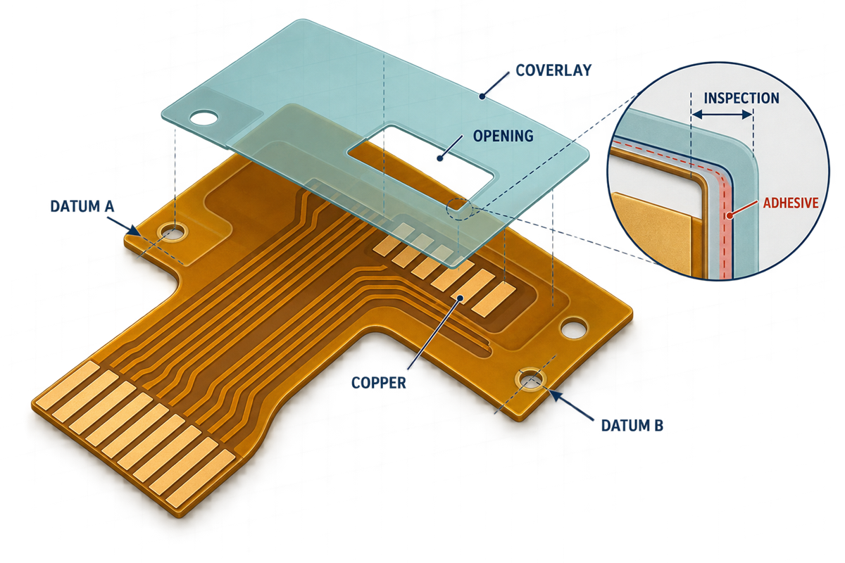
FPC coverlay registration is the finished positional relationship between a coverlay opening and the copper feature, contact area, board outline, or datum that gives the opening its function. It is not simply whether two CAD layers appear centered. A robust design defines the required exposed area, the reference basis, the allowed positional variation, the adhesive boundary, and the evidence used to accept the finished flexible circuit.
1. What Does FPC Coverlay Registration Mean?
A coverlay normally combines a dielectric film with an adhesive layer to protect the flexible circuit while leaving selected copper features exposed. The opening may serve a solder land, test point, ZIF contact area, grounding feature, or another functional interface. Registration describes where the finished opening and its edges sit relative to those features after fabrication.
Three relationships are easily confused. Coverlay-to-copper registration controls how the opening relates to a land or contact. Coverlay-to-outline registration controls its position relative to a mechanical profile. Copper-to-outline registration becomes relevant when the opening and copper are dimensioned independently from the outline. A drawing that says “opening centered” without naming the controlled feature and datum leaves the important relationship open to interpretation.
For coverlay construction and material fundamentals, see the broader FPC coverlay design guide. This article focuses on positional control, released data, and verification.
2. Define the Functional Exposed Area First
Begin with what must remain exposed in the finished part, not with an arbitrary enlargement of the copper artwork. A solder land needs sufficient accessible surface for the intended assembly process. A ZIF contact area needs the specified mating surface free from unwanted film or adhesive. A test point needs access for the agreed probe or fixture. These are different functions and may justify different drawing treatment.
Solder lands and fiducials
Identify the copper area that must remain usable and whether partial edge coverage would affect assembly or inspection. Do not assume a solder-mask clearance copied from a rigid PCB is a validated coverlay rule.
Contact fingers and test points
Define the functional contact or probing region. For connector-specific stack-up, finish, stiffener, and mating requirements, use the FPC ZIF connector design guide rather than expanding this registration requirement into a complete connector specification.
A useful drawing distinguishes the nominal opening from the minimum required exposed area. That makes the functional intent visible when the fabricator reviews whether the proposed construction and process can maintain the relationship.
3. Choose Datums That Match the Critical Relationship
The datum scheme should follow the feature that matters. If a coverlay opening protects or exposes a copper land, a local copper-referenced requirement may communicate function more directly than a long dimension chain from the board edge. If the opening must align to an enclosure or mechanical interface, an outline- or tooling-related datum may also be necessary.
Do not mix reference systems without showing how they interact. A copper feature can be within its outline-based tolerance while a coverlay opening is also within a separate outline-based tolerance, yet their worst-case relative position may still be unacceptable. The drawing should control the relationship that the product actually needs, not merely give each feature an independent coordinate.
4. Build a Registration Tolerance Stack
A coverlay clearance must accommodate more than the nominal offset in the CAD data. Depending on the construction and requirement, the stack may include coverlay-to-copper positional variation, copper-to-outline variation, outline-related location, material movement, alignment or tooling contribution, and the way the finished edge is measured. Not every term applies to every project, but omitting a relevant term does not make it disappear.
This is a design-review relationship, not a universal formula with fixed values. The terms can be combined by an agreed worst-case or statistical method only when the project, supplier, and quality plan define that method. A blanket tolerance copied from another supplier may be either unnecessarily loose or impossible for the intended construction.
The current IPC design framework separates roles: IPC-2223F is the sectional design standard for flexible and rigid-flexible printed boards, while IPC-6013F addresses qualification and performance requirements. IPC-A-600M visually interprets acceptability requirements for printed boards. Referencing a document does not replace the need to state the applicable revision, class or requirement, customer exceptions, and project-specific dimensions.
5. Treat Adhesive Flow Separately From the Film Edge
The nominal cut edge of the coverlay film is not necessarily the same as the final adhesive boundary. Supplier material data for different coverlay systems report different adhesive-flow behavior and warn that performance can vary with construction and processing. This is why a single generic squeeze-out allowance should not be applied to every material and lamination condition.
Where adhesive encroachment could contaminate or reduce a controlled exposed region, show the no-adhesive or keep-clear intent explicitly and ask for a construction-specific review. Define whether inspection controls the visible film edge, the adhesive edge, the minimum exposed copper, or another measurable boundary. Otherwise, teams may measure different features and reach different conclusions about the same part.
6. Specify Openings and Critical Areas in Released Data
The fabrication package should contain one controlled definition of the coverlay openings and a drawing that explains the critical relationships. The exact file format may vary, but the drawing and manufacturing dataset must not silently disagree. If the drawing controls a keep-clear area while the artwork controls nominal geometry, state that precedence.
- Identify the governing part number, revision, and coverlay side or layer.
- Define the nominal opening and the functional exposed region.
- Name the datum or directly control the coverlay-to-copper relationship.
- State which edge is controlled: film, adhesive, exposed copper, or another feature.
- Mark critical openings, local keep-clear areas, and any inspection locations.
- Keep fabrication artwork, drawing notes, panel data, and revision records synchronized.
- Separate firm requirements from items that remain subject to supplier review.
IPC-4203C covers classification, qualification, and quality-conformance requirements for adhesive-coated dielectric films and bonding materials used in flexible circuitry. Material designation helps procurement and documentation, but it does not by itself define the finished opening location. That relationship still belongs in the product data.
7. How Should Coverlay Registration Be Inspected?
Inspection must measure the feature named by the requirement. A visual or dimensional method may be suitable, depending on the opening, contrast, access, accuracy needed, and agreed acceptance plan. The method should state the reference feature, measurement points, reporting format, and handling of edge ambiguity. Critical locations may justify recorded measurements or first-article evidence when the project requires it.
Do not confuse bare-board coverlay inspection with assembled-board AOI. Assembly inspection can reveal downstream problems, but it is not automatically a measurement system for the film-to-copper or adhesive-to-contact relationship. The broader FPC assembly inspection guide covers post-assembly methods; coverlay registration acceptance belongs in the bare-board product definition and agreed inspection plan.
Sampling level, gauge capability, measurement resolution, acceptance class, and report format are not universal. They should be confirmed for the actual order and risk level. IPC-A-600M also notes that attributes not addressed by its visual criteria need agreement between user and supplier.
8. Common Registration Failure Modes
| Observed condition | Likely definition gap | Review action |
|---|---|---|
| Film overlaps a required exposed land or contact region | Minimum exposed area or local coverlay-to-copper relationship was not controlled | Define the functional region and local datum relationship |
| Opening is larger than needed and removes protection near conductors | Only a minimum clearance was considered | Review both exposure and protection limits |
| Adhesive reaches a contact or soldering region | Film edge was defined, adhesive boundary was not | Add a construction-specific no-adhesive requirement for review |
| Opening and copper pass separate outline tolerances but fail together | Independent datums hide the relative worst case | Control the direct functional relationship or complete the full stack |
| Drawing and artwork show different opening limits | Data precedence and revisions are unclear | Release one synchronized baseline and resolve conflicts before quotation |
| Inspection reports a different edge than engineering intended | Measurand and method were not specified | Name the edge, datum, locations, and evidence format |
FPC Coverlay Registration DFM Checklist
- What copper, contact, soldering, probing, or mechanical area must remain exposed?
- Which datum or local feature controls the opening?
- What is the nominal film opening, and which edge is the acceptance boundary?
- Which variation terms affect the final functional margin?
- Does adhesive flow need a separate keep-clear definition?
- Are copper, outline, coverlay, drawing, and panel revisions synchronized?
- Which openings are critical enough to identify individually?
- What measurement method, locations, sampling, and evidence are required?
- Which requirements are confirmed, and which remain subject to project-matched supplier review?
Technical References
Document roles and current revisions were checked against the Global Electronics Association’s status of standardization and IPC revision table. Public scope and terminology were checked against IPC’s material for board design standards, the IPC-A-600M table of contents, and the IPC-4203C table of contents. Material- and process-specific context was checked against DuPont’s Pyralux FR coverlay data sheet and Würth Elektronik’s Flex Solutions design guide. Manufacturer values are examples for named systems, not universal FPC capability limits.
Review Critical Coverlay Openings Before Release
FPCFAB can organize the available fabrication data, identify ambiguous coverlay-to-copper relationships, and coordinate DFM and quotation review with a project-matched manufacturing partner. Material selection, achievable registration, adhesive behavior, inspection scope, cost, and schedule remain subject to review and confirmation for the actual construction.