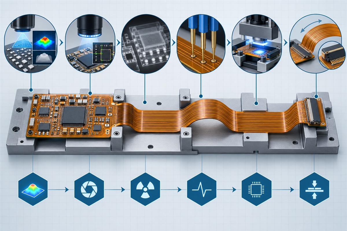
FPC assembly inspection is not a single end-of-line visual check. A useful plan combines controls for solder paste, component placement, visible and hidden joints, electrical behavior, flex-specific mechanical features, and the records needed to release or investigate the assembly.
1. Define the FPC Assembly Inspection Plan Before Quotation
Inspection becomes expensive and incomplete when it is added after the array, fixture, test points, and assembly sequence have been fixed. Before quotation, identify the assembly features that create risk: fine-pitch leads, bottom-terminated components, connectors, unsupported flex tails, local stiffener steps, double-sided population, exposed contacts, final folding, or application-specific cleanliness and traceability requirements.
The customer should also state the applicable workmanship standard, product classification, drawing requirements, and any criteria that are stricter than the industry standard. “Inspect to IPC” is not a complete instruction. The applicable document, revision, class, customer exceptions, sampling expectation, report format, and approval authority should be identified in the order package.
For an early build, separate process-validation evidence from routine production inspection. The first article may justify setup photographs, paste measurements, X-ray images, profile records, dimensional results, or a functional-test log that would not be collected for every later unit. The FPC assembly DFM guide explains why the inspection plan must be coordinated with panelization and carrier design.
2. Verify Incoming Data, Bare FPCs, and Components
Assembly inspection starts before solder paste is printed. The assembly provider needs one compatible set of fabrication data, BOM, centroid data, assembly drawings, approved substitutions, polarity references, firmware, and test instructions. A revision mismatch can produce a fully repeatable assembly of the wrong configuration.
Incoming bare-circuit checks should be distinguished from assembled-board acceptance. Depending on the project, the receiving plan may confirm the FPC part number and revision, quantity, packaging condition, exposed-contact finish, coverlay and stiffener condition, critical local thickness, electrical-test documentation, and other drawing-controlled features. IPC-6013 addresses qualification and performance requirements for flexible and rigid-flexible printed boards, while IPC-A-600 provides visual interpretation for printed-board acceptance. These bare-board controls do not replace assembly acceptance criteria.
Component controls may include manufacturer part number, supplier, lot or date information, package and value, moisture-sensitivity handling status, polarity, approved alternatives, and customer-supplied material condition. The exact records depend on the sourcing model and contract. Do not assume that “turnkey” automatically means a particular traceability level.
3. Use Solder Paste Inspection for the Printing Stage
Solder paste inspection (SPI) is intended to evaluate the printed deposit before component placement. Depending on the equipment, product presentation, and program, it may measure or compare paste presence, position, area, height, or volume. It is most useful when the FPC or carrier presents the lands at a stable height and the inspection system can view the deposit without obstruction.
SPI limits are not universal numbers. They should be developed around the stencil, aperture design, solder paste, component termination, land geometry, support condition, and the qualified printing process. A paste deposit can fall inside a general percentage limit and still be unsuitable for a specific bottom-terminated component or fine-pitch connector.
- Confirm that the paste layer and inspection program use the released assembly revision.
- Define which deposits are critical and whether they require separate limits.
- Support the flexible circuit so height variation is not mistaken for paste variation.
- Record the reaction plan for insufficient, excessive, offset, bridged, or missing deposits.
- Agree whether first-article data, trend data, or only pass/fail records must be retained.
SPI provides evidence about printing; it does not confirm that the correct component is later placed or that the solder joint is acceptable after reflow.
4. Combine Automated Optical Inspection With Visual Review
Automated optical inspection (AOI) can compare visible features such as component presence, position, orientation, polarity, marking, and selected solder-joint conditions. Its effectiveness depends on the camera view, lighting, programmed library, component geometry, surface reflectivity, and the stability of the assembly in the carrier.
Flexible circuits create specific optical challenges. A flex tail may lift away from the reference plane, a bonded stiffener may create a height step, and shiny shielding or exposed copper can change reflections. Tall parts may shadow adjacent joints. AOI programming should therefore be proven on the real array and support fixture, not only on CAD data.
Visual review remains useful for conditions that are difficult to classify automatically or that extend beyond component images. Examples include flex creases, contamination, coverlay damage, adhesive residue, scratched contact fingers, lifted stiffener edges, connector damage, handling marks, and assembly features hidden by the carrier.
5. Apply X-Ray Inspection to Defined Hidden-Joint Risks
X-ray inspection is used when relevant solder features are not directly visible, including selected ball-grid-array, bottom-terminated, overlapped, or shielded connections. It may reveal conditions such as gross bridging, missing connections, alignment problems, void patterns, or other internal features, depending on the joint geometry and imaging method.
An X-ray image is not self-interpreting. The inspection plan needs a target feature, image orientation, acceptance rule, sampling plan, and trained review. Overlapping copper, shielding layers, stiffeners, double-sided components, and the fixture can obscure or combine features in a two-dimensional image. Computed tomography or angled views may provide additional information, but availability and suitability must be confirmed for the selected production partner and project.
IPC-7095 provides design and assembly process guidance for BGA and fine-pitch BGA technology, including inspection and reliability considerations. Acceptance requirements for soldered assemblies should be tied to the applicable contract documents rather than invented from an image alone.
6. Separate Electrical Test From Functional Test
Electrical and functional testing answer different questions. A continuity or isolation check can detect defined opens, shorts, or connection errors. In-circuit testing may evaluate accessible nets or component conditions through a designed fixture. Functional testing applies power, signals, loads, firmware, or simulated interfaces to determine whether the assembly performs specified operations.
| Method | Useful For | Does Not Prove by Itself |
|---|---|---|
| Continuity / isolation | Defined opens, shorts, and connection paths. | Correct analog behavior, programmed function, mechanical fit, or solder-joint durability. |
| In-circuit test | Accessible nets, selected component values, orientation, or circuit conditions. | Every hidden connection or full product behavior when test access is limited. |
| Flying-probe test | Flexible low-volume access where a fixed fixture may not be justified. | High-throughput suitability or stable probing on an unsupported flex area. |
| Functional test | Defined product functions under specified inputs, loads, firmware, and limits. | The root cause of a failure or conformance outside the tested operating cases. |
The test specification should identify connection hardware, pin mapping, power sequence, current limits, stimulus, expected response, firmware and version, test duration, retest policy, data format, and failure disposition. If a mating connector or mechanical fixture is required, supply or define it before quotation.
Probe access deserves special attention on FPC assemblies. A probe can deflect an unsupported circuit, damage a contact surface, or produce an intermittent result. Test pads, stiffened probe zones, connector interfaces, and fixture supports should be designed together.
7. Add Flex-Specific Mechanical and Interface Checks
An electrically functional FPCA can still fail installation if its mechanical interfaces are wrong. Final inspection should address the features that control fit and handling, not only solder workmanship.
- Finished outline, slots, holes, and component or connector location from controlled datums.
- Local thickness at connector fingers or stiffened regions, measured at the specified location.
- Stiffener material, outline, alignment, adhesion, edge lifting, and transition condition.
- Contact-finger cleanliness, surface condition, width, leading edge, and insertion orientation.
- Coverlay, shielding, and adhesive condition near soldered or repeatedly handled areas.
- Component clearance from bend zones, folds, enclosure features, and mating hardware.
- Specified final fold direction, forming fixture, temporary protection, and packaging support.
A bend demonstration is not automatically a reliability test. Static installation, repeated flexing, and dynamic service impose different conditions. Any flex cycling, strain measurement, environmental exposure, or life-test requirement needs a defined method, sample construction, cycle condition, pass/fail criteria, and approval plan.
For connector-controlled details, see the FPC ZIF connector design guide. The Flexible PCB Assembly / FPCA service page describes how project files and assembly requirements are organized before production-partner review.
8. Use Different Evidence at First Article, In-Process, and Final Release
First Article
Confirms that the released data, tooling, program, materials, orientations, process settings, and test method can produce the intended configuration. Evidence may be broader than routine production records.
In-Process Control
Monitors the stages where defects originate. Examples include paste-print review, placement verification, reflow monitoring, AOI calls, material control, and defined process reactions.
Final Inspection
Confirms the completed assembly against the released acceptance plan, including workmanship, mechanical interfaces, electrical or functional results, labeling, cleanliness, and packaging.
Change Verification
Revalidates affected features after a material, component, stencil, fixture, program, process, firmware, or drawing change. The change record should identify what requires repeated evidence.
Sampling should be agreed rather than assumed. A customer may require unit-by-unit testing for one characteristic and statistical or lot-based inspection for another. The plan should also state whether rejected units may be reworked, how rework is approved, and which checks must be repeated afterward.
9. Make Inspection Records Useful for Release and Failure Analysis
A stack of images is not a controlled inspection record unless it can be connected to the correct part, revision, lot, unit or panel, date, program, criteria, and disposition. Record requirements should be proportionate to the product risk and agreed before pricing.
A practical record package may include first-article approval, inspection or test results, X-ray images for defined locations, profile records, material or component traceability, nonconformance reports, approved deviations, rework history, and final release status. Not every project needs every record.
Defect language should separate the observed condition from the suspected cause. “Connector open at pin 8” is an observation; insufficient paste, poor wetting, placement error, damaged contact, fixture movement, or a design issue are possible causes that require evidence. This distinction prevents a visible symptom from becoming an unsupported root-cause claim.
FPC Assembly Inspection Checklist for an RFQ
- Released part number, revision, BOM, centroid data, assembly drawings, and approved substitutions.
- Applicable workmanship standard, revision, class, drawing exceptions, and customer-specific criteria.
- Critical package types, polarities, hidden joints, connector interfaces, and flex-sensitive areas.
- SPI, AOI, visual, X-ray, electrical, functional, dimensional, and cleanliness requirements as applicable.
- Test points, mating hardware, fixtures, firmware, limits, sample units, and expected test outputs.
- First-article evidence, routine sampling or unit-by-unit checks, data-retention period, and report format.
- Nonconformance, deviation, rework, retest, and approval responsibilities.
- Traceability, labeling, packaging, contact protection, final fold, and delivery condition.
If some information is not yet available, identify it as an open item instead of allowing the quotation to silently assume a test scope. The FPC RFQ requirements guide provides the broader fabrication and commercial data checklist.
Technical References
IPC identifies IPC-A-610 as a post-assembly acceptance standard and J-STD-001 as requirements for soldering processes and materials. IPC notes that the documents are often used together, but they do not replace the released product requirements.
For bare flexible circuits, IPC identifies IPC-6013 as the qualification and performance specification for flexible printed boards. For BGA and fine-pitch BGA applications, IPC-7095 provides design and assembly process guidance, including inspection, rework, and reliability considerations.
Always specify the contractually applicable revision and any customer additions. These standards provide an industry framework; they do not confirm that a particular FPCFAB production partner has specific inspection equipment, certification, sampling practice, or testing capability for a project.
Need an FPC Assembly Inspection Plan Reviewed?
Send the fabrication data, BOM, centroid file, assembly drawings, critical package list, inspection criteria, test specification, quantities, and required records. FPCFAB can organize the information and coordinate an initial review with a project-matched manufacturing partner. Inspection methods, equipment availability, sampling, reports, cost, and schedule remain subject to confirmation after the complete project package is reviewed.
Request an FPCA Review Review Assembly DFM