FPC assembly DFM starts by controlling how a flexible circuit is presented to the SMT line. A flex circuit that is electrically correct can still be difficult to print, place, reflow, inspect, and depanelize if the array, tooling, support, and assembly data are treated as afterthoughts.
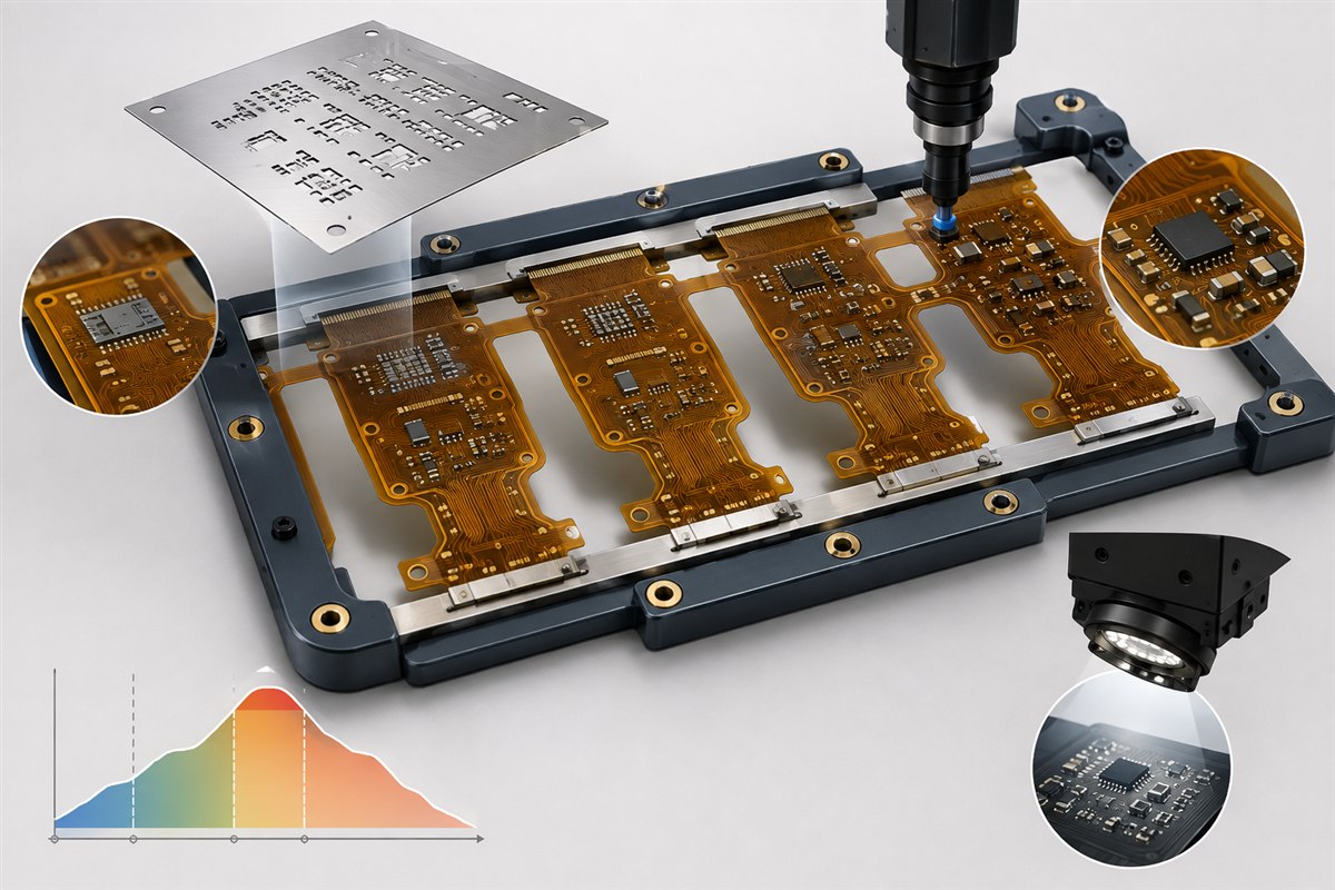
Why FPC Assembly DFM Is Different From Rigid PCB Assembly
A rigid printed board normally reaches the printer, placement machine, reflow oven, and AOI conveyor as a reasonably flat and self-supporting workpiece. An FPC does not. Thin polyimide, local copper distribution, coverlay openings, bonded stiffeners, shielding films, and cutouts can create local height changes or allow the circuit to move under process forces.
That mechanical behavior affects more than handling. If the circuit is not held flat, the stencil may not seal consistently against the lands, the placement nozzle may push the substrate away, and the AOI system may see changing focal height or reflections. A carrier can solve some of these issues, but it also changes tooling access, thermal response, cleaning access, and the sequence used to release the finished assemblies.
For this reason, FPC assembly DFM is a joint design activity. The circuit designer, FPC fabricator, component engineer, and assembly provider need to agree on the production presentation before the fabrication panel, paste layer, and placement program are frozen.
1. Define the Manufacturing Presentation Before Panelization
The first FPC assembly DFM decision is whether the product will be supplied as a fabrication array, mounted to a reusable or consumable carrier, or assembled as individual circuits in a dedicated fixture. There is no universally correct format. The choice depends on outline rigidity, component density, conveyor requirements, access from one or both sides, expected production volume, and the assembly provider’s equipment.
Fabrication Array
Multiple circuits remain connected by process rails, tabs, or other agreed breakaway features. The array can provide a repeatable machine interface, but the connection method must avoid transferring depanelization strain into active traces, solder joints, or bonded transitions.
Dedicated Carrier Fixture
The FPC is located and restrained on a rigid pallet during printing, placement, reflow, or inspection. The fixture must support critical areas without covering paste apertures, blocking nozzles, trapping flux residue, or creating uncontrolled thermal shadowing.
Temporary Support Material
A removable backing or process aid may be used for selected constructions. Adhesive selection, removal force, residue, temperature exposure, and compatibility with coverlay or shielding surfaces require validation.
Individual-Circuit Assembly
This may be practical for prototypes or unusual geometries, but it normally requires a fixture and more manual handling. The quotation should distinguish one-time tooling from recurring assembly work.
The array drawing should identify the finished circuit outline, process rails, breakaway locations, keep-out areas, tooling features, fiducials, part orientation, and any nonfunctional copper or balancing features approved for the process. Do not copy a rigid-board panel template onto a flexible circuit without reviewing how the flex will be restrained and released.
2. Separate Product Stiffeners From Assembly Support
A product stiffener and an assembly carrier perform different functions. A PI, FR-4, or metal stiffener that remains bonded to the FPC is part of the finished stack-up. It may support a connector, component area, contact finger, or mechanical attachment. A carrier is temporary process tooling used to keep the workpiece stable during manufacturing.
Confusing the two creates common DFM problems. A product stiffener may not extend far enough to support the stencil print area. It may also create a step that prevents the FPC from sitting flat on a generic carrier. Conversely, extending a permanent stiffener only to simplify assembly can increase thickness, mass, cost, and bending constraints in the final product.
The FPC assembly DFM review should map every local thickness transition. The fixture designer needs the finished thickness of base laminate, copper, coverlay, adhesive, shielding film, stiffener, and any reinforcement tape in the supported area. See the FPC stiffener design guide and FPC coverlay design guide for the product-side requirements.
3. Make Fiducials and Tooling Features Usable on the Real Assembly
Machine registration requires stable references. Global fiducials normally establish the position and rotation of the array or carrier. Local fiducials may be requested near fine-pitch devices or other placement-critical features. Their number, geometry, surface finish, copper clearance, and location must follow the selected assembly line’s vision requirements.
On an FPC, a fiducial printed on an unsupported tongue is a poor reference even if its artwork is correct. It can move or change height relative to the component lands. Place machine references in mechanically stable areas and show how those areas are supported during printing and placement.
- Identify whether each fiducial belongs to the product, fabrication array, carrier, or a combination of these.
- Keep the fiducial field free from coverlay, legend, copper clutter, and other features that reduce vision contrast.
- Define tooling holes from one controlled datum scheme rather than dimensioning them independently from multiple edges.
- Check that clamps, locating pins, vacuum ports, and conveyor rails do not interfere with components, paste apertures, or inspection views.
- Include panel orientation and bottom-side mirroring rules in the released drawing and machine data.
Tooling coordinates should agree across the mechanical drawing, fabrication data, paste data, and centroid file. A small origin or rotation mismatch can shift every placement even though each file appears valid by itself.
4. Design the Stencil Process Around Support and Paste Transfer
Within an FPC assembly DFM review, solder paste printing depends on contact between the stencil and the assembly surface, stable support beneath the lands, controlled separation, and repeatable paste release from the apertures. Flexible substrates make each condition more sensitive to fixture design and local thickness steps.
The stencil is not simply a copy of the copper land pattern. Aperture shape, reduction or expansion, foil thickness, step features, nano-coating, and local paste-volume strategy are process decisions. Fine-pitch leads, bottom-terminated components, thermal pads, and mixed component sizes may need different aperture treatments on the same assembly.
For FPC assembly DFM, the stencil supplier and assembler should review:
- paste-layer orientation and revision against the final fabrication array;
- aperture area ratio and expected transfer efficiency for the selected foil;
- support directly beneath fine-pitch and high-paste-volume locations;
- coverlay-to-pad registration and adhesive-flow risk at land edges;
- step-stencil feasibility where component requirements conflict;
- cleaning access and the effect of carrier pockets on underside contamination;
- SPI measurement strategy when solder paste inspection is required.
A one-to-one aperture rule should not be treated as a universal default. Paste volume must be engineered for the component termination, land geometry, solder alloy, stencil construction, and the assembler’s qualified process. IPC-7525C provides industry guidance for stencil design, but it does not replace product-specific process development.
5. Release Complete Placement Data, Not Just a BOM
An FPC assembly DFM package cannot stop at the BOM. A BOM identifies what should be fitted; it does not fully define where and how each component is placed. The assembly package also needs centroid or pick-and-place data, reference designators, X/Y coordinates, side, rotation, package identification, polarity information, approved substitutions, and the assembly drawing.
Rotation conventions are a frequent source of avoidable setup work. CAD systems, component libraries, and machine software may use different zero-degree definitions. The safest release includes a rendered assembly drawing or first-article image that makes orientation unambiguous for polarized capacitors, diodes, LEDs, IC pin 1, connectors, and asymmetric mechanical parts.
Land patterns should be reviewed against the component manufacturer’s current package drawing and the intended soldering process. IPC’s revision table lists IPC-7351B as no longer maintained and IPC-7352 as the newer generic land-pattern guideline. This is a useful reminder that a library name alone is not objective evidence that a footprint is correct.
For components close to a flexible transition, the DFM review should also consider nozzle access, local support, body overhang, solder-joint strain, and the installed bend condition. The FPC ZIF connector design guide covers the separate requirements for exposed contact areas and connector-side reinforcement.
6. Support the FPC During Placement Without Creating New Defects
Placement force is brief, but an unsupported FPC can deflect enough to reduce placement accuracy or disturb nearby wet paste deposits. Support should be concentrated beneath component lands while maintaining clearance for underside features, stiffener steps, test pads, and carrier retention mechanisms.
Vacuum hold-down can improve flatness when the circuit and carrier provide a stable sealing path. Mechanical clamps or low-tack retention may be more suitable for other geometries. Each method introduces different risks: blocked apertures, local distortion, adhesive contamination, handling marks, or difficult release after reflow.
Component distribution also matters. Heavy or tall parts can shift the local center of mass, while dense copper and stiffener regions change flatness and thermal response. If both sides require assembly, the process sequence and second-side retention method must be decided before the array and fixture are released.
A useful FPC assembly DFM drawing shows the supported zones, prohibited clamp zones, vacuum regions, component height restrictions, and the order in which the circuit enters and leaves each fixture. These details are often more valuable to the process engineer than a generic note saying “use carrier.”
7. Develop the Reflow Profile With the Actual Array and Carrier
FPC assembly DFM must treat the reflow profile as part of a specific assembly process, not as a generic property of “FPC.” The solder paste supplier defines the paste’s process window, component suppliers define package limits, and the FPC material system has its own thermal exposure constraints. The assembler must reconcile those limits on the real populated assembly.
The carrier affects heat transfer. A large metal or composite fixture may heat more slowly than the FPC, create local thermal mass, or change airflow around components. A profile established on a loose sample may not represent production with the carrier installed. Profiling should therefore use the intended array, fixture, component population, conveyor setup, and thermocouple locations representative of both faster- and slower-heating joints.
IPC-7530B is the current IPC guideline for temperature profiling of mass soldering processes. It treats the thermal profile as a temperature-versus-time record for the assembled product moving through the soldering system. It does not provide one universal oven recipe for every assembly.
Moisture handling should be defined in the work instruction as well. Polyimide and adhesive systems can absorb moisture, but a generic bake statement is not enough. Storage, floor life, pre-bake conditions, packaging, component moisture sensitivity, and allowable thermal history should be confirmed from the approved material and component data.
8. Plan Inspection and Test Before the First Article
Inspection coverage is part of FPC assembly DFM because the product and fixture determine what can be seen, probed, and measured. AOI requires a stable presentation, suitable access, and a programmed component library. Bottom-terminated components may require X-ray where solder joints are not optically visible. Electrical test and functional test require accessible, durable contact points and a defined connection method.
| Control Stage | What It Can Confirm | DFM Input Required |
|---|---|---|
| Solder paste inspection (SPI) | Paste presence, area, height, volume, and alignment where the equipment and surface presentation permit. | Stable support, accessible paste deposits, approved limits, and inspection-program data. |
| Automated optical inspection (AOI) | Component presence, orientation, visible solder features, polarity, and selected workmanship conditions. | Component library, reference image, stable focal plane, and unobstructed camera view. |
| X-ray inspection | Hidden solder-joint features for selected bottom-terminated packages and overlapped structures. | Inspection target, acceptance rule, fixture clearance, and traceable image requirement. |
| Electrical test | Continuity, isolation, shorts, opens, or other defined circuit checks. | Netlist, test-point access, connector or fixture definition, and test limits. |
| Functional test | Product behavior under defined power, signal, load, and firmware conditions. | Test specification, firmware, mating hardware, limits, and failure-disposition rules. |
J-STD-001J addresses soldering materials and process requirements, while IPC-A-610J provides post-assembly acceptability criteria. The purchase order or assembly drawing should state the required product class and any customer-specific criteria. Do not advertise a compliance level or inspection capability until the selected production partner has confirmed it for the project.
9. Control Depanelization, Release, and Final Handling
Assembly is not complete when the solder joints exit reflow. The FPC still has to be removed from the array or carrier without creasing the laminate, peeling a stiffener, scratching contact areas, or loading components near the release feature.
The release method should be agreed during FPC assembly DFM. Routing, punching, laser separation, cut tabs, or manual cutting may be appropriate for different constructions, but each method has tooling, edge-quality, contamination, and mechanical-stress implications. The drawing should identify the permitted cut path and the keep-out distance to conductors, solder joints, and bonded transitions.
Final handling should protect exposed contacts and prevent uncontrolled folding. Packaging may need trays, separators, support cards, protective films, or defined bend orientation. If a shipping fixture holds the product in its installed shape, that fixture is a product-packaging requirement and should not be confused with the reusable SMT carrier.
FPC Assembly DFM Data Package
For an initial engineering and quotation review, provide the following information with the normal FPC RFQ package:
- released Gerber, ODB++, or IPC-2581 data, drill files, netlist, and fabrication drawing;
- complete stack-up, coverlay, stiffener, shielding, and finished-thickness information;
- BOM with manufacturer part numbers, approved alternatives, do-not-fit status, and supply responsibility;
- centroid or pick-and-place file with coordinates, side, rotation, and reference designators;
- assembly drawings for every populated side, including polarity and connector orientation;
- paste-layer data and any known stencil or paste-volume constraints;
- proposed array, rail, fiducial, tooling-hole, and depanelization requirements;
- carrier, temporary support, or fixture assumptions, including reusable-tooling expectations;
- solder alloy, cleaning requirement, moisture handling, and process-sensitive component limits;
- acceptance class, inspection plan, test specification, firmware, mating hardware, and required reports;
- prototype quantity, production forecast, packaging method, and installed mechanical condition.
IPC-2581C is an intelligent design-to-manufacturing data format that can carry fabrication and assembly information in a structured form. Gerber plus separate BOM, centroid, drawing, and instruction files can also be used, but revision control and coordinate alignment must be managed carefully.
For an early build, the FPC prototype guide explains how to separate engineering validation from a simple low-quantity purchase.
Questions to Close Before Releasing the Order
Who Owns the Array?
Confirm whether the FPC fabricator, assembly provider, or customer creates and approves the production panel. There should be one controlled master, not conflicting panel files.
Who Owns the Carrier?
Define fixture design responsibility, one-time tooling cost, service life, storage, replacement, and whether changes require customer approval.
What Is the First-Article Evidence?
Agree which outputs are required: setup photos, SPI or AOI results, X-ray images, electrical results, profile records, dimensional checks, or a physical approval sample.
What Can the Supplier Change?
State whether the supplier may modify panel rails, fiducials, paste apertures, tooling holes, or support features, and define the approval path for each change.
How Is Revision Control Maintained?
The BOM, placement data, drawings, paste layer, fabrication files, firmware, and test limits should carry compatible revision identifiers.
How Is the Finished FPCA Protected?
Define release, cleaning, contact protection, fold condition, labeling, packaging, and transport support before production starts.
Technical References
IPC identifies IPC-2223 as the sectional design standard for flexible printed boards. IPC’s official revision table lists IPC-2223E as the current published revision while IPC-2223F remains under development.
For assembly process and acceptance terminology, IPC announced J-STD-001J and IPC-A-610J as coordinated standards covering soldering process requirements and post-assembly acceptability. IPC’s revision table also identifies IPC-7525C for stencil design, IPC-7352 for land-pattern guidance, and IPC-7530B for mass-soldering temperature profiling.
For digital manufacturing-data exchange, IPC describes IPC-2581C as a design-to-manufacturing format supporting fabrication, assembly, tooling, and DFX information. These documents provide an industry framework; the released customer drawing, approved component data, and qualified assembly process remain the project-specific control documents.
Need an FPC Assembly DFM Review?
Send the fabrication data, BOM, centroid file, assembly drawings, paste layer, stack-up, stiffener details, inspection requirements, quantities, and installed mechanical condition. FPCFAB can organize the package and coordinate an initial fabrication and assembly review with a suitable production partner. Final panelization, fixture design, stencil strategy, soldering profile, inspection capability, cost, and lead time are confirmed only after the complete project data have been reviewed.
Request an FPCA Review Check the RFQ Package