An FPC prototype is most useful when it answers specific engineering questions before a larger order. The objective may be to confirm fit, bend behavior, connector alignment, electrical continuity, impedance, assembly access, or a new material stack-up. A prototype order that has no defined validation plan can produce samples without resolving the risks that matter.
Flexible circuits combine electrical, mechanical, and material requirements in one construction. Gerber data alone may describe the copper pattern, but it does not fully define bend direction, installation shape, stiffeners, adhesives, shielding, controlled impedance, test conditions, or the intended flex duty.
This guide explains how to prepare an FPC prototype package, what to review before quotation, which factors affect cost and schedule, and how to validate the finished samples. FPCFAB coordinates project data, engineering questions, quotations, and production follow-up with project-matched manufacturing partners; fabrication is completed by the selected production source.
1. Define What the FPC Prototype Must Prove
Before requesting a quote, list the decisions that the prototype should support. This keeps the project focused and helps the engineering reviewer distinguish mandatory requirements from preferences.
- Mechanical fit: outline, tail length, connector position, stiffener thickness, installation clearance, and folded shape.
- Flex performance: one-time forming, occasional service movement, or repeated dynamic flexing.
- Electrical function: continuity, isolation, current path, impedance, signal integrity, grounding, or shielding.
- Assembly readiness: pad geometry, fiducials, panel support, component keep-out areas, connector access, and test points.
- Material confirmation: copper type, dielectric family, coverlay, adhesive, stiffener, surface finish, and any project-specific compliance requirement.
- Inspection plan: which dimensions, electrical results, visual features, reports, or samples must be reviewed before approval.
A prototype for a static battery interconnect is not evaluated in the same way as a circuit that moves continuously in a hinge. State the application and expected movement rather than using only the general word “flexible.” The FPC bend-radius guide explains why bend duty and construction must be reviewed together.
2. Prepare a Manufacturing Data Package
A complete data package reduces assumptions. Use one revision identifier across the purchase order, fabrication drawing, mechanical drawing, and data archive. Remove obsolete files from the release folder instead of asking the supplier to decide which version is current.
Fabrication image data
Provide Gerber layer data and drill information, or an agreed intelligent data format such as ODB++. Ucamco describes Gerber as the de facto open standard for PCB design-data transfer, while Siemens describes ODB++ as a structured format for transferring design information into fabrication, assembly, and test. Whichever format is used, review the exported data in an independent viewer before release.
Fabrication drawing
The drawing should identify the finished outline, layer count, finished thickness target, copper requirement, coverlay, stiffeners, surface finish, connector or contact areas, controlled-impedance requirements, tolerances, markings, testing, and any documentation requirements. Use dimensions for critical features rather than relying on a visual PDF scale.
Mechanical and application information
Include the installed shape, bend direction, bend location, mating parts, restricted areas, and available space. A simple section view or 3D assembly image can clarify details that are difficult to communicate in the PCB files. Mark whether bends occur during installation only or throughout product operation.
Electrical and test information
Provide a netlist or other agreed electrical-test data when available. Identify controlled-impedance nets, high-current paths, grounding expectations, exposed contacts, and any functional-test method. Do not assume that a standard continuity test verifies mechanical endurance, impedance, or product-level function.
For a detailed submission list, use the FPC RFQ requirements checklist.
3. Freeze the FPC Stack-Up Before Quotation
The stack-up influences thickness, stiffness, bend behavior, impedance, thermal response, and material availability. It should be treated as an engineering definition, not as a price-only choice.
| Stack-up item | Questions to confirm |
|---|---|
| Copper | Layer copper requirement, base versus finished copper, foil type where relevant, current and flex duty. |
| Polyimide and adhesive | Dielectric construction, adhesive system, finished-thickness target, and material restrictions. |
| Coverlay | Material, adhesive, opening sizes, registration allowance, exposed pads, and bend-zone transitions. |
| Stiffeners | Material, thickness, outline, bonding side, connector relationship, and tolerance-critical edges. |
| Surface finish | Finish for soldering or contact use, thickness or hardness requirements where applicable, and selective areas. |
| Shielding or reference layers | Coverage, ground connection, openings, impedance interaction, and effect on flexibility. |
Related decisions are covered in the FPC stack-up guide, coverlay design guide, and stiffener design guide.
4. Complete an FPC DFM Review
Design for manufacturability review should happen before the prototype data is released, not after material has been ordered. The review should record questions and agreed changes so that the manufactured revision remains traceable.
- Check trace width and spacing against the selected construction and production source.
- Keep vias, component pads, sharp copper corners, and abrupt width changes away from critical bend regions where possible.
- Review copper routing through bends and avoid unnecessary stress concentration.
- Confirm coverlay openings, adhesive flow allowance, exposed copper, and registration tolerance.
- Review stiffener edges, overlap, adhesive, connector insertion area, and tolerance stack-up.
- Confirm hole type, annular-ring intent, via location, access requirements, and any blind or buried structure.
- Check panelization, tooling areas, fiducials, carrier or fixture needs, and part separation method.
- Compare the mechanical drawing with the fabrication data and verify the same revision.
IPC identifies IPC-2223 as the sectional design standard for flexible and rigid-flexible printed boards, while IPC-6013 covers qualification and performance requirements for flexible printed boards. The applicable revision, performance class, acceptance criteria, and any customer-specific addendum should be stated by the buyer rather than assumed. For project-specific help, see the FPC design and DFM review service.
5. Understand Prototype Cost and Schedule Drivers
A reliable quotation depends on the actual construction. A low quantity does not automatically mean a simple project because engineering review, material preparation, tooling, programming, inspection, and reporting may still be required.
- Material availability: special polyimide, copper, adhesive, shielding film, or stiffener materials may require sourcing confirmation.
- Layer and via structure: multilayer, rigid-flex, blind-via, and controlled-depth features add process planning.
- Geometry: fine features, tight registration, unusual outlines, or tolerance-critical connector areas may affect process selection and yield risk.
- Testing and documentation: impedance coupons, electrical test, dimensional reports, microsections, material records, or special traceability should be quoted explicitly.
- Revision changes: changes after engineering release can restart review, quotation, tooling, or material preparation.
- Assembly scope: component sourcing, fixtures, stencil, programming, inspection, and functional testing create a separate set of requirements.
Do not select a prototype supplier only from a headline unit price. Compare the stated construction, included tests, assumptions, tooling, documentation, delivery terms, and change conditions. The FPC cost-factors guide provides a more detailed quotation comparison.
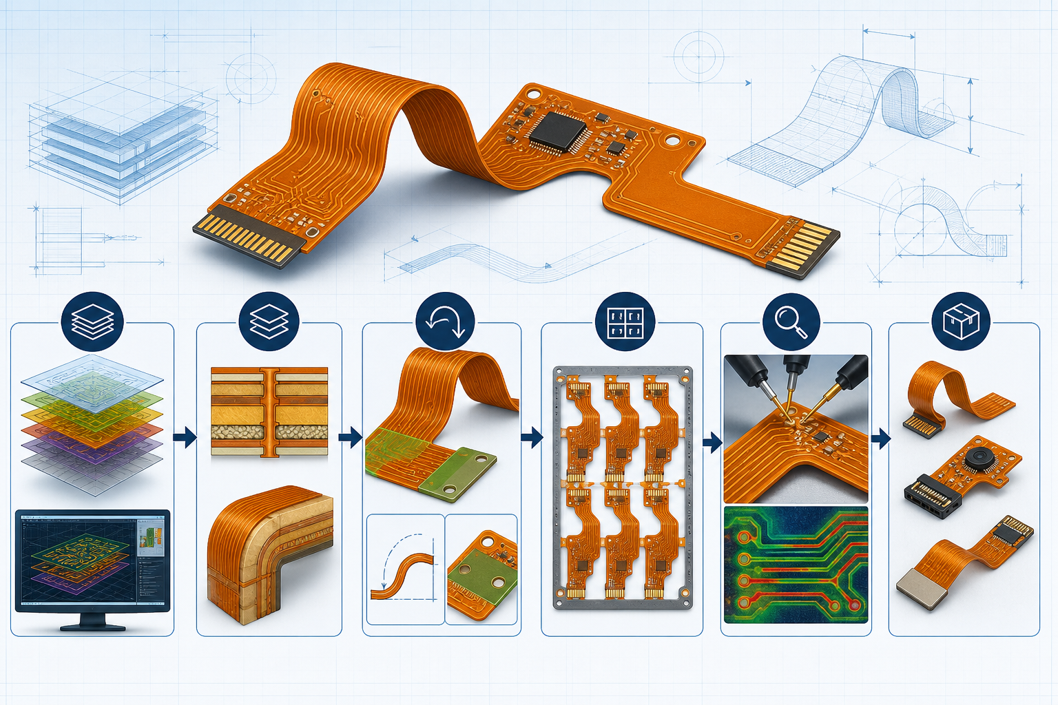
6. A Practical FPC Prototype Workflow
FPCFAB’s role is to organize the available project information, coordinate technical questions and quotation clarification, communicate with suitable production partners, and follow the agreed production and delivery-preparation scope. The selected partner remains responsible for the actual fabrication, process control, and factory-specific records.
7. Validate the Finished FPC Prototype
Validation should compare the samples with the released requirements. Keep the review evidence with the revision record so that approved features are not lost when the design moves to the next build.
- Documentation review: part number, revision, quantity, material or test records, and agreed reports.
- Visual review: outline, coverlay, exposed pads, stiffener position, markings, contamination, damage, and workmanship.
- Dimensional review: critical outline, hole, connector, stiffener, tail-length, and finished-thickness features.
- Electrical review: continuity and isolation results, plus impedance or functional checks when included in the scope.
- Mechanical review: installation fit, bend location, fold direction, connector engagement, and interference with nearby parts.
- Assembly review: soldering, component alignment, handling, fixture support, and access for inspection or test.
If a sample fails, separate design causes, data-transfer errors, manufacturing variation, assembly damage, and test-method differences. Record the evidence before changing the design; otherwise a later revision may hide the real cause without correcting it.
8. Common Reasons FPC Prototype Projects Are Delayed
- Gerber files, drawings, and purchase specifications use different revisions.
- The bend area or installed shape is not shown.
- Stiffener material, thickness, side, or outline is missing.
- Finished thickness is requested without defining the intended stack-up.
- Controlled impedance is noted but the target, tolerance, reference layer, or coupon requirement is absent.
- Special materials or certificates are requested only after quotation.
- The electrical-test or functional-test method is not available.
- Design changes continue after the engineering data has been released.
9. FPC Prototype RFQ Checklist
- Controlled Gerber and drill package, or agreed ODB++ data
- Fabrication drawing and mechanical outline
- Layer stack-up, copper, dielectric, coverlay, and finished-thickness requirements
- Stiffener, adhesive, shielding, connector, and surface-finish details
- Bend direction, bend location, installed shape, and flex duty
- Controlled-impedance, electrical-test, and functional-test requirements
- Critical dimensions, tolerances, acceptance criteria, and required reports
- Prototype quantity, spare quantity, target schedule, packaging, and delivery location
- Application, operating environment, and any project-specific compliance requirement
10. Questions Buyers Often Ask
Can an FPC prototype be quoted from Gerber files only?
A preliminary review may be possible, but an accurate production quotation normally requires construction, material, mechanical, quantity, testing, and acceptance information. Missing items should be listed as quotation assumptions rather than left implicit.
Should prototype and production use the same materials?
If the prototype is intended to validate production performance, material differences must be documented and evaluated. A readily available substitute may help answer a limited mechanical or electrical question, but it should not be treated as full production validation without review.
How many FPC prototypes should be ordered?
The quantity depends on the number of destructive and non-destructive tests, assembly trials, mechanical-fit locations, product variants, and spare samples required. Build the validation matrix first, then select the quantity.
When is an FPC prototype ready for production scaling?
Scaling should follow documented approval of the intended design, material construction, manufacturing data, inspection results, assembly behavior, and product-level validation. Any unresolved deviation should be closed or formally accepted before the next order.
Request an FPC Prototype Review
Send the files and requirements available today, including the prototype objective, quantities, target schedule, and known mechanical or test concerns. FPCFAB will organize the information, identify missing questions, and coordinate the next engineering-review and quotation step with a relevant production partner.
Technical References
- IPC Board Design Standards — overview of IPC design standards, including flexible and rigid-flexible printed-board applications.
- IPC Document Revision Table — current revision information for standards including IPC-2223 and IPC-6013.
- Ucamco Gerber resources — official Gerber format and viewer resources for PCB fabrication data.
- Siemens ODB++ resources — official information about structured PCB design-to-manufacturing data exchange.