FPC surface finish is not selected by appearance or unit price alone. The finish must protect exposed copper, preserve solderability, support the intended joining process, and remain compatible with the mechanical behavior of the flexible circuit.
A finish suitable for SMT component pads may not be the correct choice for ZIF contact fingers, wire-bond pads, membrane-switch contacts, or regions exposed to repeated handling. Nickel thickness, gold type, surface planarity, storage life, assembly temperature, contact wear, and bend-zone location all influence the final decision.
The surface finish should therefore be specified together with the FPC stack-up, copper thickness, coverlay openings, connector requirements, assembly process, operating environment, and acceptance criteria. A generic note such as “gold finish” is not sufficient for production control.
This guide compares the principal finishes used on flexible printed circuits, including ENIG, ENEPIG, OSP, immersion tin, immersion silver, and electroplated hard gold. It also explains where each finish is appropriate, what should be shown on the fabrication drawing, and which risks require additional qualification.
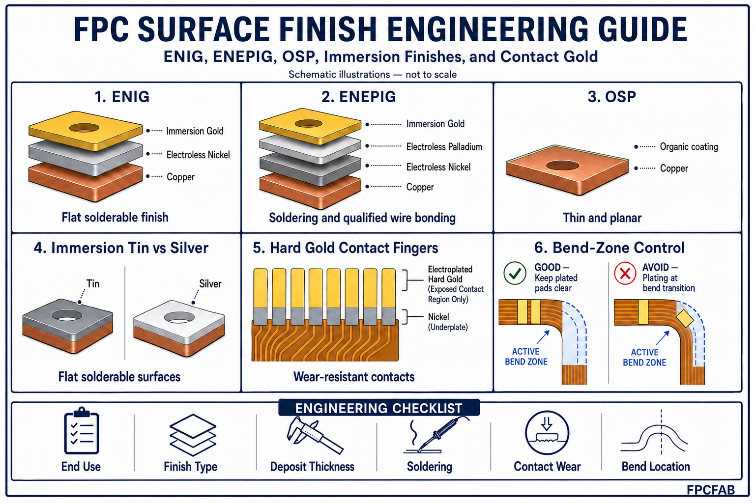
1. What an FPC Surface Finish Controls
After conductor imaging and etching, exposed copper surfaces begin to oxidize. Oxidation reduces solderability and can interfere with wire bonding, pressure contacts, connector engagement, and electrical test. The final finish provides a controlled interface between the copper conductor and the next manufacturing or service operation.
An FPC surface finish may perform several functions:
- Protect exposed copper during storage and handling
- Provide a solderable surface for SMT, through-hole, or hand-soldering operations
- Support aluminum, gold, or copper wire bonding where specified
- Provide a low-resistance contact surface for switches or connector interfaces
- Maintain pad planarity for fine-pitch component assembly
- Protect exposed test pads and programming contacts
- Provide wear resistance on contact fingers when electroplated hard gold is used
No single finish provides the best combination of solderability, wire-bond capability, contact durability, cost, flexibility, and storage life. The correct specification depends on the functional requirement of each exposed copper area.
2. Start With the End-Use Requirement
Surface-finish selection should begin with the joining and contact requirements rather than with a preferred plating name. The engineering review should identify how every exposed pad will be used.
| Application Area | Primary Requirement | Common Finish Options |
|---|---|---|
| SMT and soldered pads | Solderability, planarity, thermal-cycle compatibility | ENIG, ENEPIG, OSP, immersion tin, immersion silver |
| Fine-pitch or BGA pads | Flat pad surface and controlled deposit thickness | ENIG, ENEPIG, OSP, immersion silver |
| Gold wire bonding | Bondable surface with qualified metallurgy | ENEPIG or another specifically qualified bond finish |
| ZIF contact fingers | Insertion performance, contact resistance, dimensional control | ENIG, ENEPIG, or hard gold depending on wear requirement |
| Repeated mating contacts | Wear resistance and stable contact performance | Electroplated hard gold over nickel |
| Membrane-switch contacts | Stable contact surface and environmental resistance | ENIG, ENEPIG, or specified contact finish |
| Dynamic bend region | Minimum local stiffness and no brittle plated transition | Normally protected copper under coverlay; exposed plated features require special review |
Mixed finishes may be necessary. For example, an FPC may use ENIG on solderable pads and selective hard gold on connector fingers. When more than one finish is required, the drawing should clearly define the plated areas, masking boundaries, thickness requirements, and any permitted overlap.
3. ENIG: Electroless Nickel/Immersion Gold
ENIG consists of an electroless nickel layer deposited over copper and a thin immersion-gold layer deposited over the nickel. The gold protects the nickel surface from oxidation before soldering or contact use. ENIG is widely used because it provides a flat surface, good solderability, broad assembly compatibility, and a relatively long storage life when properly processed and handled.
Typical FPC applications include SMT pads, test pads, exposed lands, component terminals, and connector areas that do not require the wear resistance of heavy electroplated gold.
Advantages of ENIG
- Flat pad surface suitable for fine-pitch assembly
- Good solderability with common lead-free and tin-lead assembly processes
- Useful storage life when packaging and handling are controlled
- Suitable for many exposed-pad and low-wear contact applications
- Compatible with selective plating and complex FPC panel layouts
ENIG engineering risks
The electroless-nickel process must be controlled to avoid excessive nickel corrosion, commonly associated with the term “black pad.” Gold thickness, nickel-phosphorus condition, bath chemistry, dwell time, rinsing, and contamination control can affect solder-joint integrity.
ENIG should also not be treated as equivalent to electroplated hard gold. Its immersion-gold layer is thin and is not intended to provide high wear resistance for connectors subjected to many mating cycles.
The applicable industry specification is IPC-4552B for ENIG plating. Product drawings should state the required finish and applicable specification rather than relying on an uncontrolled shop-standard thickness.
4. ENEPIG: Electroless Nickel/Electroless Palladium/Immersion Gold
ENEPIG adds an electroless-palladium layer between the electroless nickel and immersion gold. The palladium acts as a diffusion barrier and provides a surface system suitable for soldering and qualified wire-bonding applications.
ENEPIG is often selected when one flexible circuit must support multiple interconnection methods, such as SMT soldering, gold wire bonding, and contact interfaces. It is particularly useful for advanced packaging, sensor assemblies, camera modules, medical electronics, and compact FPCA constructions where different pad functions share the same circuit.
Advantages of ENEPIG
- Flat surface suitable for fine-pitch assembly
- Supports soldering and qualified wire-bonding processes
- Palladium layer limits direct interaction between nickel and gold
- Useful where several joining technologies are required on one FPC
- Can provide improved process flexibility for high-reliability assemblies
ENEPIG costs more than ENIG and requires tighter control of nickel, palladium, and gold deposition. Wire-bond capability should be qualified using the actual wire material, pad geometry, bonding equipment, assembly cleaning process, and environmental requirements. A generic ENEPIG callout does not by itself guarantee acceptable bond strength.
ENEPIG requirements are covered by IPC-4556A. Where wire bonding is critical, the drawing and procurement specification should define the applicable bonding process and required validation data.
5. OSP: Organic Solderability Preservative
OSP is a thin organic coating applied directly to exposed copper. It protects the copper surface from oxidation while preserving a highly planar pad geometry. Because OSP does not add a substantial metallic layer, it can be attractive for thin FPC constructions and fine-pitch soldering.
Advantages of OSP
- Very flat soldering surface
- Low deposited thickness and minimal effect on local stiffness
- No nickel barrier layer
- Cost-effective for suitable high-volume assembly processes
- Compatible with fine-pitch solder paste printing when properly controlled
OSP is sensitive to handling, contamination, storage conditions, and repeated thermal exposure. The coating can be damaged by fingerprints, abrasion, aggressive cleaning, or an unsuitable assembly sequence. Multiple reflow cycles and long storage periods require product-specific evaluation.
OSP is not normally selected for wear contacts or conventional wire bonding. It is best applied where the exposed copper will be soldered within a controlled assembly and storage window. High-temperature OSP requirements are addressed by IPC-4555.
6. Immersion Tin
Immersion tin deposits a thin tin layer directly over copper through a chemical displacement process. It produces a flat, solderable surface and can be suitable for fine-pitch assembly, press-fit features, and applications where a nickel-containing finish is undesirable.
Advantages of immersion tin
- Flat surface for fine-pitch soldering
- Good initial solderability when processing and storage are controlled
- No nickel layer between the solder and copper
- Suitable for selected press-fit and assembly applications
Tin and copper form an intermetallic compound that continues to grow during storage. Deposit thickness, copper condition, storage time, humidity, packaging, and assembly temperature therefore influence the remaining solderable tin at the surface.
Tin-whisker risk, finish handling, and the intended product life should also be reviewed. Immersion tin should not be specified solely because it is flat or lead-free. The application must be compatible with the finish metallurgy and storage controls.
Immersion-tin plating is covered by IPC-4554. Acceptance requirements should be coordinated with solderability testing, packaging, and the planned time between fabrication and assembly.
7. Immersion Silver
Immersion silver is a thin metallic finish deposited directly over copper. It provides a flat surface with good solderability and is used for fine-pitch assembly, high-frequency designs, and applications where a nickel barrier may be undesirable.
Because silver has high electrical conductivity and avoids the nickel layer used in ENIG and ENEPIG, it may be considered for RF and high-speed interconnects after the complete conductor geometry and insertion-loss requirements have been reviewed.
Handling and packaging are important. Sulfur-containing environments, fingerprints, contamination, and poor storage control can discolor or degrade the finish. Anti-tarnish processing, clean packaging materials, moisture protection, and a defined assembly window should form part of the procurement plan.
Immersion silver is not a wear-resistant connector finish. Exposed areas that will experience repeated mechanical contact require a separately qualified contact system.
8. Electroplated Hard Gold for Contact Fingers
Electroplated hard gold is normally deposited over an electrolytic nickel underplate. Small amounts of alloying elements are incorporated into the gold deposit to improve hardness and wear resistance. This finish is used for connector fingers, sliding contacts, test interfaces, and other surfaces subjected to repeated mechanical engagement.
Hard gold must be distinguished from immersion gold. Immersion gold protects the underlying nickel and supports soldering or low-wear contact use, but it does not provide the same deposit thickness or wear performance as electroplated hard gold.
Critical hard-gold controls
- Gold thickness and hardness range
- Nickel-underplate thickness
- Plated area and plating-bus removal method
- Contact-finger width, pitch, and edge position
- Surface roughness, porosity, and cosmetic acceptance
- Number of insertion or mating cycles
- Finished insertion thickness where a ZIF connector is used
Hard gold is generally not preferred on solder joints because a substantial gold deposit can affect solder-joint metallurgy. When a contact finger also requires soldering, the plated areas and solderable areas should be separated and clearly defined.
9. Surface Finish and FPC Bend Reliability
The influence of a surface finish on flexibility is local rather than uniform. Most conductors inside an active bend zone remain protected by coverlay and do not receive a final metallic finish. Problems arise when exposed pads, nickel-bearing finishes, hard-gold transitions, plating boundaries, or abrupt coverlay openings are placed within or immediately beside the bend region.
Nickel is considerably less ductile than annealed copper. A nickel-bearing finish on an exposed conductor can create a localized stiffness change and a potential crack-initiation point when subjected to repeated bending. Thick plated deposits and abrupt transitions increase this concern.
Good bend-zone practice includes:
- Keep solder pads and connector contacts outside the defined active bend zone
- Avoid hard-gold and nickel-plating boundaries in repeatedly flexed regions
- Maintain smooth conductor routing through the bend
- Keep coverlay, stiffener, shielding, and plating transitions away from the same bend line
- Use the finished construction—not base copper thickness alone—to calculate bend strain
- Validate dynamic applications using representative production samples and actual flex conditions
For further mechanical-design guidance, review the FPC Bend Radius Design Guide, the FPC Stack-Up Design Guide, and the FPC Copper Foil Guide.
10. Engineering Comparison of Common FPC Finishes
| Finish | Typical Strength | Main Limitation | Common FPC Use |
|---|---|---|---|
| ENIG | Flat, solderable, established supply chain | Nickel-process control and limited wear resistance | SMT pads, test pads, general exposed lands |
| ENEPIG | Soldering plus qualified wire-bond capability | Higher cost and tighter process control | Advanced FPCA, wire bonding, multifunction pads |
| OSP | Very flat, thin, cost-effective | Handling, storage, and thermal-cycle sensitivity | Controlled high-volume solder assembly |
| Immersion Tin | Flat solderable surface without nickel | Intermetallic growth and storage control | Fine-pitch soldering and selected press-fit use |
| Immersion Silver | Flat, conductive, suitable for selected RF use | Tarnish and contamination sensitivity | Fine-pitch, RF, and high-speed designs |
| Hard Gold | Wear-resistant contact surface | Cost, plating-bus requirements, not preferred for soldering | ZIF fingers and repeated-mating contacts |
This comparison is an engineering screen, not a substitute for product qualification. Finish supplier, chemical system, process capability, pad geometry, assembly profile, storage condition, and end-use environment can change actual performance.
11. Common Surface-Finish Failure Modes
Surface-finish defects are not always visible during incoming inspection. Some become apparent only after reflow, wire bonding, connector insertion, environmental exposure, or extended storage.
| Failure Mode | Possible Cause | Engineering Control |
|---|---|---|
| Poor solder wetting | Oxidation, contamination, aged finish, inadequate deposit | Control storage, packaging, cleanliness, thickness, and solderability testing |
| Nickel corrosion or black-pad condition | Uncontrolled ENIG chemistry or excessive corrosion | Qualified chemistry, bath control, cross-section and process monitoring |
| Wire-bond lift | Incorrect finish, contamination, unsuitable deposit structure | Specify bonding system and validate actual wire-bond process |
| Contact wear | Immersion finish used for excessive mating cycles | Use qualified hard gold and define cycle requirements |
| Tarnish or discoloration | Sulfur exposure, moisture, poor packaging, handling | Controlled materials, clean handling, sealed packaging, defined shelf life |
| Cracking near a pad | Plated feature or stiffness transition located near the bend | Move pad and plating boundary outside the active bend zone |
| Variable contact resistance | Porosity, contamination, wear, insufficient deposit | Define finish thickness, contact force, inspection, and mating-cycle testing |
Inspection may include visual examination, X-ray fluorescence thickness measurement, solderability testing, tape testing where applicable, cross-section analysis, wire-bond pull or shear testing, contact-resistance measurement, and environmental conditioning. The inspection plan should match the actual risk rather than applying every test to every product.
12. What to Specify on the Fabrication Drawing
A production drawing should state more than the abbreviated finish name. Clear requirements reduce quotation differences and prevent the fabricator from making assumptions about contact life, assembly compatibility, or deposit thickness.
Recommended drawing and RFQ information includes:
- Surface-finish type using its full industry name
- Applicable IPC specification and revision where required
- Minimum and maximum deposit thickness for controlled layers
- Selective-plating boundaries and areas excluded from plating
- Hard-gold thickness, nickel underplate, and contact area
- Wire material and wire-bonding requirement
- Solder alloy, reflow count, and peak assembly temperature
- Connector type, finished insertion thickness, and mating-cycle requirement
- Maximum storage period and packaging requirement where critical
- Special solderability, contact-resistance, or bond-strength acceptance criteria
- Inspection class and required qualification records
If the customer permits several finish options, the drawing should identify the approved alternatives rather than using an open note such as “ENIG or equivalent.” Different finishes may require different pad dimensions, process flows, assembly windows, and reliability validation.
13. Surface Finish, Coverlay, and Pad Geometry
Finish performance cannot be separated from coverlay-opening design. The finished exposed pad depends on coverlay registration, adhesive squeeze-out, copper-feature tolerance, surface-finish buildup, and the clearance required by the assembly process.
For ZIF fingers and fine-pitch pads, the design review should verify:
- Finished copper exposure after coverlay and plating tolerances
- Minimum dielectric web between adjacent openings
- Adhesive-flow limits near contact and soldering areas
- Plating coverage at pad edges
- Stiffener registration and finished connector thickness
- Distance from the pad edge to the active bend region
These relationships are discussed further in the FPC Coverlay Design Guide and the FPC Stiffener Design Guide.
14. Qualification and Supplier Control
A surface-finish callout is only effective when supported by a capable and controlled fabrication process. Supplier approval should consider chemical-bath control, analysis frequency, deposit-thickness capability, coupon design, traceability, handling, packaging, and corrective-action history.
Critical programs may require production-lot records, XRF results, solderability data, cross-section reports, ionic-cleanliness results, wire-bond qualification, or connector-cycle testing. Automotive, medical, aerospace, and high-reliability industrial products should define these requirements before quotation because they affect process planning, sample preparation, testing cost, and lead time.
Relevant standards may include IPC-4552 for ENIG, IPC-4555 for high-temperature OSP, IPC-4556 for ENEPIG, J-STD-003 for printed-board solderability testing, IPC-A-600 for printed-board acceptability, and IPC-1601 for handling and storage. The latest applicable revision and customer-specific requirements should be confirmed during contract review.
15. How FPCFAB Supports Surface-Finish Selection
FPCFAB reviews the FPC surface finish together with copper construction, pad geometry, coverlay openings, stiffeners, connector interfaces, assembly temperature, wire bonding, bend regions, storage conditions, and inspection requirements.
Our Flexible PCB Manufacturing service supports single-sided, double-sided, and multilayer flexible circuits from prototype and NPI builds through production.
Customers may provide completed Gerber or ODB++ data and a fabrication drawing, or request an FPC Design & DFM Review before finalizing surface finish, contact-finger construction, coverlay openings, and assembly details.
Conclusion
Reliable FPC surface-finish selection requires more than choosing between ENIG and hard gold. The correct finish depends on soldering, wire bonding, contact wear, storage life, pad planarity, assembly temperature, connector geometry, environmental exposure, and bend-zone location.
ENIG remains a practical general-purpose finish for many solderable FPC pads. ENEPIG provides additional capability where soldering and qualified wire bonding must coexist. OSP, immersion tin, and immersion silver offer flat surfaces for suitable controlled processes, while electroplated hard gold is reserved for contacts requiring defined wear performance.
The fabrication drawing should define the functional requirement, finish type, controlled thickness, plated area, inspection criteria, and applicable standard. When the finish is evaluated as part of the complete flexible-circuit construction, manufacturing risk and assembly variation can be reduced before production release.
For an engineering review or quotation, send your Gerber or ODB++ data, fabrication drawing, stack-up, surface-finish requirements, connector information, assembly process, quantities, and application conditions to FPCFAB.