FPC copper foil is not selected by copper weight alone. The foil manufacturing method, temper, grain structure, surface treatment, base thickness, plated-copper buildup, and relationship to the bend axis all influence how a flexible circuit behaves during fabrication, assembly, installation, and service.
Rolled-annealed copper is widely associated with high-flex applications, while electrodeposited copper is often selected for cost-effective static-flex and general interconnect designs. That distinction is useful as a starting point, but it is not a complete material specification. Modern electrodeposited foils include high-elongation and flex-grade products, and rolled foils also vary in temper, surface profile, treatment, and fatigue performance.
The correct selection therefore depends on the finished construction rather than the foil name alone. A thin, well-balanced circuit with suitable conductor routing can outperform a poorly detailed construction made with a nominally superior foil. Conversely, heavy copper, excessive plating, sharp trace transitions, vias in the bend zone, or an unfavorable material transition can shorten flex life even when rolled-annealed foil is used.
This guide explains how engineering and purchasing teams should specify copper foil type, thickness, orientation, plating, performance requirements, and qualification data before releasing an FPC design for production.
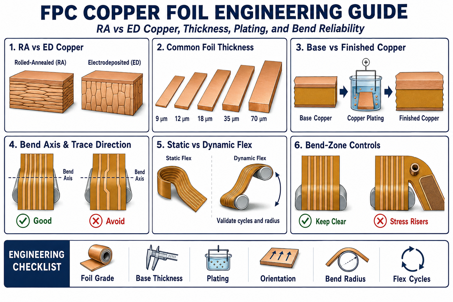
1. What FPC Copper Foil Controls
Copper foil performs several functions at the same time. It carries current and signals, forms pads and contact fingers, provides plated-through-hole interconnection where required, and remains part of the mechanical structure whenever the circuit is bent.
Its influence extends beyond electrical conductivity. Copper selection affects:
- Flexural fatigue life under repeated bending
- Minimum practical bend radius and forming behavior
- Finished circuit thickness and neutral-axis location
- Current-carrying capability, resistance, and temperature rise
- Fine-line etching capability and conductor-width control
- Adhesion to the polyimide or bonding system
- High-frequency conductor loss associated with surface profile
- Dimensional movement during etching and lamination
- Via reliability where the foil is combined with electrodeposited plating
These requirements must be reviewed together. Selecting thicker copper to reduce resistance, for example, also increases bending strain and makes fine-line etching more difficult. A reliable design balances electrical demand against the required mechanical movement and manufacturing process.
2. Copper-Foil Terminology and Applicable Standards
FPC copper foil drawings frequently use the abbreviations RA and ED, but these identify manufacturing families rather than complete performance grades.
- RA copper: Rolled-annealed copper foil produced by mechanical rolling followed by controlled heat treatment.
- ED copper: Electrodeposited copper foil formed electrochemically, commonly on a rotating cathode drum, then treated as required for bonding and environmental stability.
- Base copper: The copper thickness present in the laminate before subsequent circuit plating.
- Finished copper: The final conductor thickness after the applicable plating and fabrication processes.
- Drum side and matte side: Terms used for the two surfaces of conventional ED foil. Their topography and surface treatment may differ.
- Machine direction and transverse direction: Material directions associated with foil production. Directional properties can be relevant to rolled foil and must not be confused with conductor direction through the bend zone.
IPC-4562B addresses metal foils used in printed wiring applications. Flexible metal-clad dielectric materials are covered by IPC-4204, while IPC-2223 provides sectional design requirements for flexible and rigid-flex printed boards. Finished-board qualification and performance requirements are addressed by IPC-6013.
A drawing may reference these standards, but the procurement documentation should still define the actual application. The foil designation alone does not communicate bend radius, number of cycles, operating temperature, conductor geometry, plating condition, or the required test method.
3. Rolled-Annealed Copper Foil
Rolled-annealed copper begins as copper stock that is reduced to foil thickness through successive rolling operations. Annealing develops a more ductile microstructure and relieves work hardening. The resulting grain morphology is generally elongated and directionally influenced by the rolling process.
RA copper is commonly selected for circuits that must withstand repeated flexing, tight forming, or severe installation movement. Typical applications include printer mechanisms, camera modules, foldable assemblies, moving sensor connections, and compact electromechanical products.
Engineering advantages commonly associated with appropriate RA foil include:
- High ductility and favorable fatigue behavior
- Good suitability for dynamic-flex and repeated-forming applications
- Availability in thin gauges for low-profile constructions
- Relatively smooth foil options for fine circuitry and high-frequency designs
RA should not be treated as a universal guarantee of flex life. Foil temper, grain development, surface treatment, laminate manufacturing, trace orientation, final copper thickness, and bending strain remain important. A low-profile or high-temperature material may also require a different foil treatment from a general-purpose flex laminate.
4. Electrodeposited Copper Foil
Electrodeposited copper is formed from copper ions in an electrolytic process. Copper is deposited onto a rotating cathode drum and removed as a continuous foil. The surface against the drum is typically smoother, while the opposite surface develops a different profile and may receive additional bonding and protective treatments.
Conventional ED foil has often been associated with rigid PCB laminates and static-flex FPC constructions. It is cost-effective, widely available, and suitable for many products that bend only during installation or experience limited movement in service.
However, ED copper is not one single mechanical grade. Suppliers offer high-elongation, high-temperature-elongation, low-profile, very-low-profile, and other engineered ED products. Some flex-grade ED foils provide substantially better fatigue performance than conventional ED foil and may be qualified for demanding applications.
The material callout should therefore identify the required property set or approved laminate, not merely state “ED copper.” When flex performance is critical, review the supplier data for tensile strength, elongation, surface profile, peel strength, thermal exposure, and flexural endurance in the finished material system.
5. RA Copper vs ED Copper: Engineering Comparison
| Review Area | Rolled-Annealed Copper | Electrodeposited Copper |
|---|---|---|
| Manufacturing method | Mechanical rolling followed by controlled annealing | Electrodeposition onto a cathode drum followed by applicable treatment |
| Typical grain morphology | Directionally influenced and developed through rolling and annealing | Columnar, granular, or specially engineered deposit structure depending on grade |
| Common application | Dynamic flex, repeated forming, and demanding bend conditions | Static flex, installation flex, general interconnects, and qualified flex-grade applications |
| Flex performance | Often favorable, but dependent on temper, thickness, orientation, and complete construction | Varies widely; conventional and high-elongation flex grades should not be treated as equivalent |
| Surface profile | Generally available in smooth or treated profiles | Drum-side and matte-side characteristics vary; low-profile grades are available |
| Fine-line capability | Good with a suitable thin, low-profile material system | Good with an appropriate thin, low-profile ED grade and controlled etching |
| Cost and availability | May carry a material premium | Broad availability and often cost-effective, depending on grade |
| Specification approach | Define approved material, thickness, property requirements, and direction where applicable | Define ED grade or approved laminate; do not rely on the generic ED designation |
This FPC copper foil comparison should be used as an engineering screen, not as a substitute for qualification. For a cable that is folded once during installation, either suitable RA or ED material may meet the requirement. For millions of operating cycles, the material, trace layout, stack-up, bend radius, motion path, and test method must be evaluated as one system.
6. Selecting Copper Foil Thickness
Common nominal FPC copper foil thicknesses include approximately 9 µm, 12 µm, 18 µm, 35 µm, and 70 µm. These are often described commercially as 1/4 oz, 1/3 oz, 1/2 oz, 1 oz, and 2 oz copper. The micrometre value and supplier tolerance should control the engineering review because weight-based descriptions are nominal.
| Nominal Copper | Approximate Thickness | Typical Engineering Consideration |
|---|---|---|
| 1/4 oz | 9 µm | Very thin flex constructions, fine circuitry, low-current signal applications, and demanding flex requirements |
| 1/3 oz | 12 µm | Thin signal circuits where flexibility and controlled conductor formation are important |
| 1/2 oz | 18 µm | Common balance of flexibility, fine-line capability, and moderate electrical demand |
| 1 oz | 35 µm | Higher current or lower resistance, with increased bending strain and etching demand |
| 2 oz | 70 µm | Power and heater applications; requires careful bend, spacing, etching, and thermal review |
Thinner copper generally reduces the strain at the outer conductor surface for a given bend condition and improves fine-feature etching. It also raises conductor resistance and may require wider traces, parallel current paths, or thermal-spreading features.
Thicker copper reduces DC resistance and can improve current capacity, but it increases stiffness and local strain. It also produces greater conductor sidewall taper during subtractive etching, which can limit minimum line width and spacing. For heavy-copper FPC, conductor geometry and bend placement should be reviewed early rather than after the electrical layout is complete.
Current capacity must not be selected from copper thickness alone. Trace width, allowable temperature rise, ambient conditions, heat sinking, dielectric construction, copper distribution, duty cycle, and adjacent heat sources all affect the result.
7. Base Copper vs Finished Copper Thickness
One of the most common drawing problems is an ambiguous copper-thickness note. “35 µm copper” may refer to the starting foil, the minimum finished conductor thickness, or a nominal value after plating. These are not interchangeable.
In double-sided and multilayer flexible circuits with plated-through holes, copper is deposited in the holes and on accessible conductor surfaces during fabrication. The final surface-conductor thickness may therefore include both the base foil and subsequent copper plating. The actual buildup depends on the process sequence, pattern density, current distribution, panel position, and plating controls.
This difference matters mechanically. A circuit designed around 18 µm base copper may have a materially thicker finished conductor in plated areas. If the plated surface extends through an active bend region, the added electrodeposited copper can become a fatigue-limiting part of the construction.
A production drawing should distinguish among:
- Nominal base-copper thickness
- Minimum finished copper in plated areas
- Minimum copper in plated-through holes or microvias
- Areas where selective plating or plating exclusion is required
- Surface-finish requirements, which are separate from copper thickness
The complete layer construction should also be coordinated with the FPC Stack-Up Design Guide, especially where plated copper changes symmetry or finished thickness.
8. Copper Selection for Static and Dynamic Flexing
“Flexible circuit” does not define how the product moves. FPC copper foil selection should begin by classifying the actual mechanical condition.
Installation or Static Flex
A static-flex circuit is normally bent for assembly or installation and then remains in position. It may still experience handling, vibration, thermal movement, or service access, but it is not intended to cycle continuously. Suitable RA or ED constructions can be used, depending on the bend severity and qualification requirements.
Dynamic Flex
A dynamic-flex circuit operates through repeated motion. The design must define the expected cycle count, bend radius, bend angle, movement frequency, travel path, temperature range, and whether the bend is one-directional or fully reversed. RA copper is commonly preferred, but an approved flex-grade ED material may also be considered when supported by relevant test data.
Dynamic performance depends strongly on the finished circuit. Important controls include:
- Thin, balanced, and preferably symmetric bend-zone construction
- Conductors routed smoothly across the bend region
- No vias, pads, test points, or abrupt width changes in the active bend zone
- Controlled plating so unnecessary copper is not added in the flexing region
- Coverlay, shielding, adhesive, and stiffener transitions kept outside the active bend zone
- A bend radius and motion path that do not introduce creasing or torsion
For bend-radius and construction guidance, refer to the FPC Bend Radius Design Guide.
9. Rolling Direction, Bend Axis, and Trace Orientation
Three different directions are often confused in FPC copper foil applications: the foil production direction, the conductor direction, and the mechanical bend axis. They should be identified separately on critical dynamic-flex designs.
Conductors should normally cross a simple bend region as directly as practical. In most layouts this means the traces run approximately perpendicular to the bend axis. Smooth arcs, uniform trace widths, and gradual transitions reduce stress concentration. Sharp corners, neck-downs, staggered discontinuities, and branch points should be placed outside the active bend region.
Rolled foil may show directional mechanical behavior because its microstructure is influenced by rolling and annealing. However, a universal rule such as “always place the rolling direction parallel to the trace” is not reliable for every foil grade and laminate. Supplier terminology, laminate orientation, circuit-panel orientation, and the actual bending mode must be confirmed together.
Where directional flex performance is critical, the drawing and material specification should identify:
- Machine direction and transverse direction of the approved laminate
- Circuit orientation within the production panel
- Bend-axis direction in the finished assembly
- Trace direction through the active bend region
- Applicable directional test data or a representative flex coupon
This control is especially important when narrow circuits are nested at different angles to improve panel utilization. Material yield should not override an orientation requirement that is necessary for fatigue life.
10. Plated Copper, Vias, and Bend-Zone Reliability
The base foil and plated copper do not necessarily have the same microstructure or fatigue behavior. A circuit may use RA base foil while its through holes and surface conductors receive electrodeposited copper during fabrication.
Plated-through holes should be kept out of active bend zones whenever practical. The hole wall, annular ring, local resin geometry, and copper-thickness transition create a mechanically discontinuous region. Repeated bending near that transition can initiate barrel cracking, pad lifting, or conductor fatigue.
When layer-to-layer interconnection is required near a moving region:
- Move the via field into a supported or non-flexing area
- Provide sufficient distance between the via transition and the active bend
- Avoid placing stiffener edges directly at the via field boundary
- Review teardrops, pad geometry, coverlay support, and copper balance
- Use a representative qualification coupon when service movement is severe
Button plating, selective plating, or alternative process sequences may be considered when the design requires plated interconnection but should minimize surface copper buildup. These options must be agreed with the fabricator before the drawing is finalized.
11. Surface Profile, Adhesion, and Signal Performance
Copper surface treatment is necessary to achieve reliable bonding to the dielectric or adhesive system. A rougher treated surface can improve mechanical anchoring, but excessive profile may complicate fine-line formation and increase conductor loss as operating frequency rises.
For general FPC interconnects, peel strength, thermal durability, chemical compatibility, and long-term adhesion normally drive the material choice. For high-speed FPC copper foil applications, including digital, radio-frequency, antenna, and other low-loss designs, the copper profile becomes part of the electrical model because current distribution is increasingly concentrated near the conductor surface.
Low-profile and very-low-profile foils can reduce the roughness contribution to insertion loss, but the complete laminate must still meet adhesion and fabrication requirements. The review should include the foil treatment, polyimide system, adhesive or adhesiveless construction, line geometry, impedance target, frequency range, and expected environmental exposure.
Copper roughness should not be specified through an isolated marketing name. Use an approved laminate data sheet or define the measurable surface-profile and electrical requirements with the material supplier and fabricator.
12. Etching, Dimensional Control, and Manufacturability
FPC copper foil selection affects the conductor image that can be produced consistently. Subtractive etching removes copper vertically and laterally, so thicker foil generally creates greater undercut and a more pronounced trapezoidal conductor profile.
Minimum line width and spacing must be matched to the copper thickness, copper profile, resist process, etchant control, panel size, and required tolerance. A geometry that is practical in 12 µm or 18 µm copper may not be production-capable in 35 µm or 70 µm copper without changing the process or accepting a different tolerance.
Etching also releases stress and changes the copper distribution across the polyimide. This can produce dimensional movement, curl, or handling distortion, particularly in thin adhesiveless constructions and unbalanced conductor patterns. Accurate tooling compensation requires stable source data, known material orientation, and realistic fabrication tolerances.
Manufacturability should be reviewed before copper thickness is frozen when the design includes:
- Fine-pitch connector fingers or narrow pad gaps
- Heavy-current conductors adjacent to fine signal routing
- Tight controlled-impedance tolerances
- Large copper-free windows or strongly unbalanced copper distribution
- Long narrow circuits with critical dimensional registration
- Selective plating or multiple finished-copper requirements
13. FPC Copper Foil Requirements on the Drawing
A useful fabrication drawing defines the functional requirement without forcing an unsuitable process. For standard products, an approved flexible copper-clad laminate designation may communicate the foil, dielectric, bonding system, and thickness more clearly than separate generic notes.
Depending on the application, the drawing or controlled material specification should include:
- Approved laminate manufacturer and material series, or an agreed equivalent
- Copper foil family and performance grade where necessary
- Nominal base-copper thickness and applicable tolerance
- Minimum finished surface copper and hole-wall copper
- Material direction and circuit orientation where flex performance is directional
- Static or dynamic flex classification and expected number of cycles
- Bend radius, bend angle, motion path, and operating temperature
- Electrical requirements such as resistance, current, temperature rise, or impedance
- Required qualification method and acceptance criteria
- Lot traceability, certificate of conformance, or material test report requirements
A note such as “use RA copper for flexibility” is incomplete because it does not define the actual mechanical duty. Likewise, “one-ounce finished copper” should state where the minimum applies and whether the value includes plating.
14. Inspection and Qualification
Incoming FPC copper foil documentation can confirm the laminate identity, foil thickness, lot, and specified properties, but finished-circuit reliability should be verified at the appropriate level. Inspection and testing may include:
- Microsection measurement of base and plated copper
- Conductor-width, spacing, and sidewall-profile inspection
- Peel-strength or bond-integrity evaluation for the laminate system
- Tensile strength and elongation testing where specified
- Resistance monitoring during representative bend cycling
- Cross-section or failure analysis after flex testing
- Thermal exposure followed by adhesion and flex evaluation
IPC-TM-650 Method 2.4.3.1 describes flexural fatigue and ductility testing for flexible printed wiring. A useful qualification coupon should represent the production material, copper thickness, plating condition, dielectric stack, conductor width, bend radius, and movement mode. Testing a bare foil strip does not fully represent a finished FPC.
For critical dynamic products, electrical continuity should be monitored during cycling rather than checked only at the end. A gradual resistance increase can indicate conductor damage before an open circuit occurs.
15. Common FPC Copper Foil Selection Mistakes
- Assuming all RA copper has identical fatigue performance: Temper, foil grade, treatment, thickness, and laminate processing still matter.
- Rejecting all ED copper for flex applications: Conventional ED and engineered flex-grade ED products have different property ranges.
- Specifying copper weight without clarifying thickness: Use nominal micrometre values and applicable tolerances for engineering control.
- Ignoring plated-copper buildup: Finished conductors in plated areas can be considerably thicker than the base foil.
- Using heavy copper through an active bend: Lower resistance may be offset by higher stiffness and fatigue strain.
- Confusing trace direction with foil rolling direction: Both should be reviewed against the bend axis, but they are not the same design variable.
- Placing vias or abrupt copper transitions in the bend zone: Local stiffness and stress concentration can dominate the material advantage.
- Qualifying only the raw material: The finished laminate, plating, routing, coverlay, and assembly condition determine product performance.
How FPCFAB Supports Copper-Foil Selection and Production
FPCFAB reviews FPC copper foil type, base thickness, finished copper, plating distribution, conductor geometry, bend direction, material transitions, coverlay, shielding, stiffeners, connector areas, and assembly requirements before production.
Our Flexible PCB Manufacturing service supports single-sided, double-sided, and multilayer flexible circuits from prototypes and NPI builds through production.
Customers may provide completed Gerber or ODB++ data and a fabrication drawing, or request an FPC Design & DFM Review before finalizing the copper construction and bend-zone details.
Conclusion
Reliable FPC copper foil selection requires more than choosing RA or ED and assigning a nominal copper weight. Foil grade, temper, grain morphology, surface profile, base thickness, plated-copper buildup, trace routing, bend orientation, laminate construction, and operating movement must be evaluated together.
RA copper remains a common choice for demanding dynamic-flex applications, but its performance is not automatic. Flex-grade ED materials can also be appropriate when supported by relevant data and qualification. The correct decision is the one that meets the electrical, mechanical, fabrication, assembly, and service requirements of the finished circuit.
For an engineering review or quotation, send your Gerber or ODB++ data, fabrication drawing, stack-up, copper requirements, bend conditions, assembly information, quantities, and application details to FPCFAB.