FPC stiffener design is not limited to adding a rigid backing beneath a flexible circuit. A stiffener changes the local thickness, bending stiffness, flatness, load path, connector engagement, assembly support, and handling characteristics of the finished part.
Many production problems begin with an incomplete stiffener definition. The Gerber data may show the outline, but the drawing does not identify the material, nominal thickness, adhesive system, finished local thickness, location tolerance, edge relationship, or mechanical function. The manufacturer is then forced to make assumptions that may affect connector fit, component coplanarity, bend reliability, or assembly yield.
There is no universal stiffener material or thickness suitable for every flexible printed circuit. A thin polyimide reinforcement beneath a soldered termination serves a different purpose from an FR-4 stiffener behind a ZIF contact area or a stainless-steel support beneath a dimensionally critical component region.
This guide explains how engineering and purchasing teams should define FPC stiffener materials, thickness, bonding, edge location, dimensional tolerance, connector support, assembly requirements, inspection criteria, and quotation data before releasing the design for production.
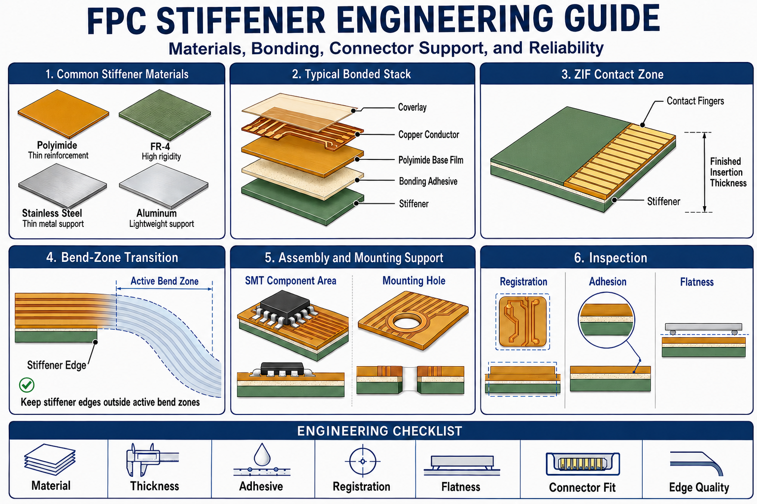
1. What an FPC Stiffener Controls
A stiffener reinforces a selected area without converting the complete flexible circuit into a rigid board. Its function should be defined according to the mechanical and assembly requirement at that location.
Common stiffener functions include:
- Supporting SMT components, connectors, switches, sensors, or soldered terminals
- Providing the required insertion thickness for ZIF and other contact-finger interfaces
- Maintaining local flatness during solder-paste printing, component placement, and reflow
- Reducing pad lifting and trace-to-pad strain under insertion or handling load
- Reinforcing mounting holes, slots, cable exits, or mechanically fastened regions
- Improving handling stability during fabrication, testing, assembly, and final installation
- Distributing concentrated mechanical load over a larger area of the flexible circuit
- Providing controlled local thickness for enclosure, connector, or fixture interfaces
A stiffener does not remove mechanical stress. It changes where the flexible circuit bends and where strain is transferred. The stiffener edge therefore becomes a structural transition that must be coordinated with the copper pattern, coverlay, shielding, pressure-sensitive adhesive, component layout, and installation geometry.
The complete thickness relationship should also be reviewed against the FPC Stack-Up Design Guide, because the base laminate, copper, plating, coverlay, bonding adhesive, and stiffener all contribute to the finished local construction.
2. Terminology and Applicable Standards
In flexible-circuit documentation, the terms stiffener and reinforcement normally describe a nonfunctional material bonded to a selected area to provide mechanical support. The stiffener may be polyimide, FR-4, stainless steel, aluminum, or another approved material.
An FR-4 stiffener without conductor circuitry is not automatically a rigid section of a rigid-flex printed board. A true rigid-flex construction integrates rigid and flexible circuit layers into one interconnected printed-board structure. This distinction affects stack-up documentation, fabrication processing, inspection, testing, and quotation.
IPC-2223 establishes sectional design requirements for flexible and rigid-flexible printed boards and recognizes flexible constructions with or without stiffeners. IPC-6013 addresses qualification and performance requirements for flexible and rigid-flexible printed boards.
These standards provide an industry framework, but they do not replace the released fabrication drawing, connector specification, assembly drawing, material approval requirements, or customer-specific acceptance criteria. Critical finished dimensions, tolerances, adhesive conditions, and mechanical interfaces should be defined explicitly rather than left to a general note such as “add stiffener as required.”
3. Common FPC Stiffener Materials
Material selection should begin with the required support function, available thickness, operating environment, assembly temperature, dimensional tolerance, and electrical relationship to the circuit.
| Stiffener Material | Typical Engineering Use | Key Review Points |
|---|---|---|
| Polyimide | Thin reinforcement, soldered termination support, local thickness buildup, and gradual transition areas | Film thickness, thermal compatibility, adhesive system, edge profile, flexibility, and dimensional stability |
| FR-4 | ZIF contacts, connector zones, component areas, mounting regions, and locations requiring higher rigidity | Laminate thickness, glass weave, edge quality, moisture condition, flatness, machining tolerance, and assembly temperature |
| Stainless steel | Thin high-stiffness support, wear-resistant interfaces, compact structures, and dimensionally critical areas | Alloy, thickness tolerance, burr control, edge treatment, corrosion protection, weight, grounding, and electrical clearance |
| Aluminum | Lightweight metal reinforcement, local flatness, mechanical support, or thermal-spreading applications | Alloy, surface treatment, electrical insulation, galvanic compatibility, adhesive bonding, edge condition, and thermal expansion |
Polyimide and FR-4 are the most common choices for general flexible-circuit reinforcement, but they are not interchangeable. Polyimide can provide a thinner and more gradual mechanical transition. FR-4 normally provides greater local rigidity and is widely used where connector engagement, component support, or controlled insertion thickness is required.
Metal stiffeners can achieve high rigidity at a relatively low thickness, but they introduce additional considerations. Conductive material must maintain the required electrical clearance from exposed copper, test points, pads, component terminals, and shielding contacts unless intentional grounding is specified. Burrs, sharp corners, poorly controlled edges, or an unsuitable surface condition can damage the FPC or interfere with adhesive bonding.
4. Adhesive and Bonding Systems
The stiffener adhesive is part of the finished mechanical stack. Its thickness and flow affect local height, bond strength, edge condition, dimensional tolerance, flatness, and thermal performance.
Common bonding approaches include:
- Thermosetting or heat-activated adhesive: Commonly used where the stiffener is laminated under controlled heat and pressure. The process can provide a stable permanent bond when the adhesive, surface preparation, pressure, temperature, and cure cycle are correctly matched.
- Pressure-sensitive adhesive (PSA): Used for selected positioning, mounting, or lower-temperature applications. PSA simplifies attachment but may have different creep, temperature, chemical-resistance, and long-term load characteristics from a thermosetting system.
- Specified structural adhesive system: May be required for metal stiffeners, unusual materials, high-temperature service, demanding peel loads, or customer-qualified constructions.
The nominal adhesive thickness should not be omitted from the stack-up. Finished bondline thickness may vary with material topography, copper distribution, coverlay steps, lamination pressure, adhesive flow, and local openings. Where the stiffener overlaps coverlay, shielding film, plated copper, or another reinforcement layer, the resulting step must be included in the finished-thickness calculation.
Stiffener adhesive should develop continuous contact without unacceptable voiding, contamination, edge lifting, or excessive squeeze-out. Adhesive entering connector fingers, solderable pads, test points, holes, slots, or profile edges can create functional and assembly problems. The acceptable condition should be judged on the finished product, not only from the nominal pre-lamination artwork.
5. Selecting Stiffener Thickness and Finished Local Construction
Stiffener thickness should be selected from the required mechanical function and finished interface—not from a standard material list alone. A connector-engagement zone, an SMT support area, and a mounting-hole reinforcement may require different constructions even when they are located on the same FPC.
The finished local thickness may include:
- Flexible base laminate
- Base and plated copper thickness
- Coverlay film and adhesive
- Surface finish on exposed contact areas
- Stiffener bonding adhesive
- Polyimide, FR-4, or metal stiffener
- Shielding film, PSA, or other local materials where applicable
Adding the nominal values provides only a preliminary estimate. Adhesive compression, resin flow, copper distribution, plated buildup, coverlay steps, material tolerance, and measurement location all influence the finished result.
Polyimide stiffeners are commonly selected from thin commercial film options when moderate reinforcement or a gradual thickness transition is required. FR-4 stiffeners are available over a much wider thickness range and can provide substantially greater rigidity. Metal stiffeners may provide high stiffness with less thickness, but their conductive nature and edge condition require additional control.
These commercial material ranges must not be converted into a universal design rule. If the local thickness interfaces with a connector, socket, enclosure, clamp, fixture, heat spreader, or mechanical datum, the controlling component drawing should specify the required finished thickness and tolerance.
| Design Requirement | Thickness Review |
|---|---|
| General handling support | Select enough reinforcement to prevent unwanted folding or distortion without creating an unnecessarily severe transition |
| ZIF or contact-finger interface | Control the finished insertion thickness, parallelism, leading edge, finger location, and connector-specific tolerance |
| SMT component area | Review local flatness, paste printing, placement support, reflow compatibility, and inspection access |
| Mounting hole or slot | Review bearing load, washer or fastener area, hole-to-stiffener registration, edge distance, and crack resistance |
| Metal reinforcement | Review rigidity, insulation clearance, adhesive bondline, burr condition, surface treatment, and weight |
6. ZIF and Contact-Finger Stiffener Design
ZIF connectors and similar contact interfaces are among the most tolerance-sensitive FPC stiffener applications. The connector normally engages the completed flexible tail, not the nominal stiffener material by itself.
The review should therefore use the finished construction at the actual insertion zone. Important requirements include:
- Finished insertion thickness and permitted tolerance
- Contact-finger width, pitch, length, and position
- Stiffener material and nominal thickness
- Bonding adhesive and expected bondline thickness
- Surface finish and any plated thickness on the contact side
- Leading-edge geometry, corner radius, chamfer, or profile requirement
- Tail width, outline tolerance, and connector-entry clearance
- Distance from the stiffener edge to the active bend region
- Acceptable adhesive squeeze-out near the insertion edge
- Insertion and withdrawal cycle requirement
The stiffener is commonly bonded to the side opposite the contact fingers, but the complete connector specification remains controlling. A generic final thickness should not be assumed from another connector family, even when the pitch and number of contacts appear similar.
The stiffener must extend far enough behind the contact region to support insertion load and maintain alignment. However, extending it unnecessarily toward the active bend can shorten the compliant length and concentrate strain at the stiffener edge.
The relationship among the finger pattern, coverlay gang opening, surface finish, stiffener position, and final outline should be dimensioned from common datums. Independent artwork origins or poorly coordinated compensation can produce an electrically correct tail that does not fit the connector.
7. Stiffener Support for Components and FPCA
When components are mounted directly on a flexible circuit, a stiffener can provide the local rigidity required for solder-paste printing, pick-and-place support, reflow soldering, inspection, testing, and final handling.
The reinforcement should be reviewed with the assembly drawing rather than added after the bare-board design is complete. The review should consider:
- Component package size, mass, and terminal geometry
- Pad layout and coverlay-opening relationship
- Stencil support and solder-paste print stability
- Placement pressure and local circuit deflection
- Reflow temperature and number of thermal cycles
- Component coplanarity and finished local flatness
- Inspection, cleaning, electrical test, and rework access
- Cable movement and mechanical load after assembly
- Fixture, panelization, and depaneling requirements
The stiffener outline should support the complete functional area without placing an abrupt unsupported step directly beneath a solder joint, pad neck, or mechanically loaded component termination. A poorly positioned edge may allow the component area to rock or flex even when the stiffener material itself is sufficiently rigid.
For projects that include component mounting, connector installation, or complete module delivery, the FPC stiffener should be reviewed together with the Flexible PCB Assembly / FPCA requirements before fabrication tooling and solder-paste stencils are released.
8. Stiffener Edges and Bend-Zone Transitions
The end of a stiffener creates a rapid change in bending stiffness. If that edge is positioned inside an active bend zone, repeated movement can concentrate strain in the copper, coverlay, adhesive, or base film near the transition.
Good transition design normally includes the following principles:
- Keep the stiffener edge outside the active bend zone
- Maintain enough unsupported flex length for the specified movement
- Avoid placing vias, pads, holes, or abrupt conductor-width changes at the edge
- Avoid routing conductors parallel to the stiffener edge where the local strain is high
- Use smooth copper transitions and rounded geometry where mechanically appropriate
- Coordinate stiffener, coverlay, shielding-film, PSA, and enclosure transition lines
- Avoid stacking several material terminations at exactly the same location
- Control sharp corners, burrs, and projecting adhesive at the stiffener perimeter
Where practical, staggering the termination lines of different local materials can reduce one severe thickness step. The exact offset should be determined from the construction, available space, movement direction, bend radius, and manufacturing capability rather than copied from a generic drawing.
Polyimide reinforcement can provide a more gradual transition than a thick FR-4 or metal stiffener, but the complete structure still requires review. A thin material can create a high local strain if its edge, adhesive, copper geometry, and bend location are poorly coordinated.
For static-flex, installation-flex, and dynamic-flex applications, review the transition against the actual movement requirement described in the FPC Bend Radius Design Guide. Coverlay and adhesive behavior near the transition are discussed in the FPC Coverlay Design Guide.
9. Registration, Outline, and Dimensional Tolerance
Stiffener location affects more than appearance. Misregistration can change connector fit, hole alignment, local support, pad loading, bend length, outline clearance, and assembly position.
The fabrication drawing should define the functional relationship between the stiffener and the following features where applicable:
- FPC final outline
- Contact fingers and connector datum
- Mounting holes, slots, notches, and tooling features
- SMT pads and component centers
- Coverlay openings and local exposed copper
- Active bend-zone boundaries
- Shielding, PSA, and secondary reinforcement layers
- Critical enclosure or assembly interfaces
Dimensions should be based on common functional datums. Locating the contact fingers from one artwork origin, the stiffener from another, and the final profile from an unrelated reference can create an uncontrolled tolerance stack.
The drawing should distinguish between nominal stiffener dimensions, permitted location tolerance, final local thickness, hole or slot tolerance, and acceptable edge condition. A tightly controlled connector interface may require more specific measurement points than a general handling reinforcement.
Double-sided or stacked reinforcements also require alignment control. Opposing stiffeners that are unintentionally offset can twist the flexible circuit, create an uneven load path, or produce local thickness variation during clamping and assembly.
10. Mounting Holes, Slots, and Mechanically Loaded Areas
Mounting holes and slots in a flexible circuit may experience clamp load, fastener pressure, repeated handling, cable pull, or enclosure movement. A local stiffener can distribute this load and reduce distortion of the surrounding flex material.
The stiffener design should be coordinated with the finished hole or slot rather than added as an independent backing feature. The review should include:
- Plated-through, nonplated, or mechanically punched feature type
- Finished hole or slot dimensions
- Stiffener-to-hole registration tolerance
- Distance from the hole to the stiffener and FPC outlines
- Copper, coverlay, and exposed-pad clearance
- Fastener head, washer, boss, pin, or locating-feature geometry
- Expected tensile, shear, bearing, and compressive loads
- Required number of assembly and service cycles
- Burr, debris, adhesive, and edge-condition limits
A stiffener opening that is smaller than the FPC hole can interfere with assembly. An excessively large opening may leave the flexible laminate unsupported at the load-bearing edge. Where a pin or fastener passes through several materials, the released drawing should define which finished feature controls the mechanical fit.
For plated holes, the reinforcement must not introduce uncontrolled stress into the plated barrel or annular ring. For nonplated mounting holes, the design should maintain enough supported material to resist tearing, elongation, or local delamination under the specified assembly load.
11. Multiple Stiffeners and Local Material Integration
A flexible circuit may contain several stiffeners with different functions. One region may require an FR-4 connector stiffener, another may use polyimide beneath soldered terminals, and a third may require metal reinforcement for local flatness or mechanical support.
Each stiffener should be identified separately in the fabrication data. A practical drawing normally defines:
- Stiffener reference or part designation
- Material type and approved equivalent
- Nominal material thickness
- Adhesive type and nominal thickness
- Side of the FPC on which the stiffener is bonded
- Outline, holes, slots, and critical dimensions
- Location tolerance relative to functional datums
- Required finished local thickness
- Inspection and acceptance requirements
Opposing stiffeners can increase rigidity and balance a local structure, but their outlines and bondlines must be coordinated. Misaligned top and bottom reinforcements can create bow, twist, uneven clamping pressure, or a concentrated bending line.
Stacked local materials require the same review. A stiffener bonded over coverlay, shielding film, pressure-sensitive adhesive, plated copper, or another reinforcement may produce an uneven bond surface and additional thickness variation. The drawing should identify intentional overlaps instead of relying on separate Gerber layers that do not show the completed cross-section.
Where shielding film requires grounding, the metal stiffener, conductive adhesive, grounding window, and exposed copper must be treated as an electrical interface. Accidental contact should not be accepted as a grounding method.
12. Engineering Review for Metal Stiffeners
Stainless-steel and aluminum stiffeners are selected when the required rigidity, thickness, wear resistance, flatness, weight, or thermal behavior cannot be achieved efficiently with polyimide or FR-4.
Metal reinforcement introduces requirements that are not present with an ordinary dielectric stiffener:
- Electrical clearance from conductors, pads, component terminals, and test points
- Defined grounding or electrical isolation where applicable
- Alloy, temper, and thickness tolerance
- Surface finish, oxide condition, cleanliness, and adhesive compatibility
- Burr direction, edge break, corner radius, and cut-edge condition
- Galvanic compatibility with adjacent metals and the operating environment
- Coefficient-of-thermal-expansion mismatch
- Thermal path and insulation requirements
- Weight, magnetic behavior, and enclosure interaction where functionally relevant
A metal stiffener should not be described only by generic terms such as “steel plate” or “aluminum sheet” when its properties affect the product. The drawing may need to specify alloy, thickness, surface treatment, flatness, edge condition, and bonding surface.
Using a metal stiffener as a heat spreader also requires a defined thermal path. Bonding a metal plate behind the FPC does not by itself establish effective heat transfer. The dielectric layers, adhesive thickness, copper distribution, component location, contact area, and enclosure interface determine the actual thermal behavior.
13. Stiffener Conversion and Bonding Process
Stiffeners may be produced by routing, punching, laser cutting, die cutting, chemical processing, or another qualified conversion method. The selected process affects edge quality, dimensional tolerance, tooling cost, minimum feature size, burr condition, and production volume.
A typical bonding sequence may include:
- Material verification and conditioning
- Stiffener and adhesive conversion
- FPC and stiffener surface preparation
- Tooling, alignment, or optical registration
- Lay-up and controlled bonding
- Heat, pressure, and cure where required
- Cooling or stabilization under controlled conditions
- Final profiling, cleaning, and dimensional inspection
- Adhesion, flatness, thickness, and visual verification
The exact sequence depends on the material system and whether stiffener bonding occurs before or after final FPC profiling. Early bonding can improve panel handling and registration in some constructions. Later bonding may be appropriate for selected shapes, metal parts, or assembly-specific processes.
Bonding pressure should be distributed without damaging components, plated features, raised copper, or unsupported flex areas. The process must also prevent trapped contamination, localized voiding, stiffener movement, excessive adhesive flow, and permanent distortion.
Manufacturer review should be completed before hard tooling or assembly fixtures are released. Projects with several stiffeners, tight connector tolerances, unusual metals, controlled local thickness, or complex alignment requirements may benefit from an early FPC Design & DFM Review.
14. Common Stiffener Defects and Engineering Causes
| Observed Condition | Possible Contributors | Engineering or Process Review |
|---|---|---|
| Stiffener misregistration | Artwork mismatch, tooling error, material movement, poor datum control, or bonding shift | Review common datums, tooling strategy, compensation, location tolerance, and inspection method |
| Edge lifting or delamination | Contamination, inadequate surface preparation, insufficient pressure or cure, incompatible adhesive, or high peel load | Review material compatibility, cleaning, bondline, cure condition, edge geometry, and service load |
| Voids beneath the stiffener | Uneven topography, trapped air, insufficient adhesive flow, surface contamination, or nonuniform pressure | Review local stack-up, adhesive thickness, copper distribution, lay-up, pressure, and venting path |
| Adhesive squeeze-out | Excess adhesive, high pressure, unsuitable flow characteristics, insufficient clearance, or excessive temperature | Review adhesive selection, bondline thickness, tooling, process parameters, and keep-out areas |
| Finished thickness out of tolerance | Incorrect material, adhesive variation, compression, plating buildup, overlapping films, or incorrect measurement location | Review the complete local stack, material tolerances, measurement datum, and process capability |
| Bow or twist | Asymmetrical construction, misaligned opposing stiffeners, uneven cure, material stress, or nonuniform copper distribution | Review mechanical balance, stiffener alignment, cooling, panel support, and local material symmetry |
| Copper cracking near the stiffener edge | Edge inside the bend zone, insufficient flex length, abrupt thickness transition, unfavorable routing, or excessive bend radius reduction | Review the actual movement path, conductor geometry, edge location, coverlay transition, and bend validation |
| Connector insertion failure | Incorrect finished thickness, poor tail width, stiffener offset, adhesive at the leading edge, or contact-finger misregistration | Review the connector drawing, insertion-zone dimensions, profile tolerance, final thickness, and inspection data |
| FPC damage at a metal edge | Burrs, sharp corners, poor edge break, movement against the metal, or inadequate adhesive coverage | Review metal conversion, edge specification, corner radius, bonding coverage, and mechanical loading |
A visible condition does not always reveal the primary cause. Dimensional measurement, cross-section analysis, peel evaluation, material verification, thermal-history review, surface inspection, and process records may be required before corrective action is approved.
15. Inspection and Acceptance Requirements
Stiffener inspection should be based on the product function, applicable performance class, released drawing, approved material system, and agreed customer requirements. Visual appearance alone is not sufficient where the stiffener controls connector fit, local thickness, mounting position, or assembly flatness.
Typical inspection items include:
- Stiffener material and nominal thickness
- Adhesive type and bondline construction
- Stiffener outline, holes, slots, and corner geometry
- Location relative to contact fingers, pads, components, holes, and final profile
- Finished local thickness at the specified measurement area
- Flatness, bow, twist, and component-support condition
- Adhesion, edge lifting, voids, wrinkles, and delamination
- Adhesive squeeze-out and contamination of functional areas
- Metal burrs, sharp edges, corrosion, and surface treatment
- Electrical clearance or intentional grounding of conductive stiffeners
- Connector-tail width, leading edge, and insertion fit
- Condition of the FPC at the stiffener transition
Inspection data should identify the measurement location and method. A finished-thickness value taken over a copper-free area may not represent the thickness over plated contact fingers or a local coverlay overlap. Connector-critical regions may require a defined gauge area, sampling plan, and recording method.
IPC-6013 provides qualification and performance requirements for flexible and rigid-flexible printed boards, while IPC-A-600 provides visual interpretation of printed-board acceptance conditions. Customer drawings may establish additional dimensional, cosmetic, mechanical, or documentation requirements. Any condition not adequately defined should be agreed between the user and supplier before production.
16. Information Required for Stiffener Review and Quotation
A quotation cannot reliably evaluate an FPC stiffener from its outline alone. The supplier should understand what the reinforcement must support and which dimensions are functionally critical.
Provide the following information whenever available:
- Gerber, ODB++, or other production data
- Fabrication drawing and completed FPC stack-up
- Separate stiffener drawing or clearly identified stiffener layer
- Stiffener material, grade, and approved equivalent requirements
- Nominal stiffener and adhesive thickness
- Required finished local thickness and tolerance
- Stiffener side, outline, holes, slots, and location dimensions
- Functional datums and critical registration tolerances
- ZIF or other connector manufacturer and part number
- Connector drawing and insertion-thickness requirement
- Component, SMT, soldering, and assembly information
- Bend location, direction, radius, angle, and cycle requirement
- Mounting loads, fasteners, enclosure interfaces, or mechanical constraints
- Metal surface treatment, grounding, or insulation requirements
- Operating temperature, chemicals, moisture, vibration, and service environment
- Inspection class, test requirements, reports, and traceability
- Prototype, pilot-run, and production quantities
- Target lead time and delivery schedule
If the stiffener construction has not been finalized, provide the functional requirement instead of selecting a material from a previous product. Connector data, desired local rigidity, available space, assembly process, bend condition, and environmental requirement allow the manufacturer to propose a preliminary construction for review.
For a broader list of files and specifications needed for pricing, see How to Prepare an FPC RFQ.
FPC Stiffener DFM Checklist
| Review Area | Questions to Confirm |
|---|---|
| Function | Does each stiffener provide connector support, component support, mounting reinforcement, handling stability, controlled thickness, or another defined function? |
| Material | Are the polyimide, FR-4, stainless-steel, aluminum, or other material requirements clearly identified? |
| Thickness | Are nominal material thickness, adhesive thickness, finished local thickness, tolerance, and measurement location defined? |
| Adhesive | Is the bonding system suitable for the material, assembly temperature, operating environment, and mechanical load? |
| Connector | Are contact-finger geometry, insertion thickness, tail width, leading edge, surface finish, and stiffener position coordinated with the connector drawing? |
| Assembly | Does the stiffener provide enough support for printing, placement, soldering, inspection, test, and rework? |
| Bend transition | Is the stiffener edge outside the active bend zone, with adequate unsupported flex length and no stacked abrupt transitions? |
| Registration | Are stiffener position, holes, slots, contacts, components, and final profile controlled from common functional datums? |
| Metal stiffener | Are alloy, surface treatment, burr condition, electrical clearance, grounding, corrosion, and thermal requirements addressed? |
| Inspection | Are adhesion, edge lifting, voiding, squeeze-out, flatness, thickness, connector fit, and dimensional acceptance criteria defined? |
How FPC Stiffeners Affect Cost and Lead Time
Stiffener cost depends on more than the material area. Material type, thickness, adhesive system, number of separate pieces, conversion method, tooling, registration tolerance, bonding process, inspection, and production volume all affect the quotation.
Cost and lead time may increase when the design requires:
- Uncommon FR-4, polyimide, or metal thicknesses
- Several different stiffener materials on one FPC
- Tight connector-related thickness and location tolerances
- Complex profiles, small holes, narrow slots, or fine alignment features
- Laser-cut or precision-machined metal components
- Special metal alloys, surface treatment, insulation, or edge finishing
- Controlled adhesive-flow or bondline requirements
- Double-sided or stacked reinforcements
- Critical flatness, coplanarity, or connector-fit inspection
- Special testing, reports, traceability, or customer qualification
Standard material options, practical tolerances, shared functional datums, and early connector review can reduce unnecessary tooling and repeated engineering changes. Cost reduction should not remove the reinforcement required for solder-joint support, connector engagement, mounting strength, or bend reliability.
How FPCFAB Supports Stiffener Design and Production
FPCFAB reviews stiffener material, thickness, adhesive system, finished local construction, connector support, component area, mounting features, bend transitions, metal-edge requirements, dimensional tolerance, inspection, and assembly conditions before production.
Our Flexible PCB Manufacturing service supports single-sided, double-sided, and multilayer FPC projects with polyimide, FR-4, metal, and project-specific reinforcement requirements.
Customers may provide completed production data or request an FPC Design & DFM Review before finalizing connector thickness, stiffener construction, bend location, assembly support, and manufacturing tolerances.
Conclusion
Reliable FPC stiffener design begins with a defined mechanical function. Material and thickness alone do not determine the result. Adhesive bondline, finished local thickness, connector engagement, stiffener position, copper routing, coverlay, assembly load, bend transition, dimensional tolerance, and inspection method must be evaluated as one construction.
The released drawing should identify each reinforcement material, bonding system, location, critical dimension, finished interface, and acceptance requirement. Connector zones, component areas, mounting features, metal supports, and active bend transitions deserve separate controls rather than one general stiffener note.
Send your Gerber or ODB++ data, fabrication drawing, stack-up, stiffener requirements, connector information, assembly files, quantities, and application conditions to FPCFAB for engineering review and quotation support.