An accurate flexible printed circuit quotation requires more than the finished dimensions, layer count, and order quantity. The FPC manufacturer must understand the electrical, mechanical, material, dimensional, testing, assembly, and commercial requirements before confirming manufacturability, tooling cost, unit pricing, and lead time.
Incomplete quotation packages often lead to repeated technical clarification, provisional pricing, incorrect assumptions, or quotation revisions after design review. Details such as laminate construction, copper type, finished copper thickness, coverlay openings, stiffener configuration, controlled impedance, bend conditions, surface finish, electrical testing, panel delivery, and assembly scope can materially affect the production process and final cost.
This guide explains the essential FPC RFQ requirements for prototype, pilot-run, and volume-production projects. It is intended for hardware engineers, PCB designers, procurement engineers, sourcing managers, project teams, and supply-chain professionals preparing flexible PCB or FPCA quotation packages.
1. Why Complete FPC RFQ Requirements Matter
A complete RFQ allows the manufacturer to evaluate the actual design rather than quote against a generic or assumed construction. Flexible circuits contain more interacting mechanical and material variables than conventional rigid PCBs, particularly when the design includes dynamic flexing, multilayer construction, local stiffeners, connector fingers, rigid-flex transitions, fine-pitch features, or controlled-impedance traces.
Clear quotation data enables the manufacturer to determine:
- Whether the proposed stack-up is compatible with the required bend performance
- Which polyimide laminate, adhesive system, and copper type should be used
- Whether the minimum trace width, spacing, annular ring, and drill sizes are manufacturable
- How coverlay, exposed pads, connector fingers, and stiffeners should be processed
- Whether controlled impedance, laser drilling, via filling, or special plating is required
- Which electrical test, inspection, and acceptance criteria apply
- How the circuit should be panelized for fabrication, assembly, and shipment
- Whether the requested quantity, target lead time, and delivery schedule are realistic
Complete FPC RFQ requirements also reduce the risk of commercial changes after purchase order placement. If important specifications are missing, the initial quotation may be based on standard assumptions that do not match the final released design.
For example, a quotation based on standard electrodeposited copper may no longer be valid if the final application requires rolled annealed copper for repeated flexing. Similarly, a standard polyimide stiffener cannot be priced accurately if the connector interface ultimately requires a controlled-thickness FR-4 or stainless steel stiffener.
For this reason, an RFQ package should be treated as a preliminary manufacturing data set rather than a simple request containing only dimensions, layer count, and quantity.
2. Provide Complete Design and Fabrication Data
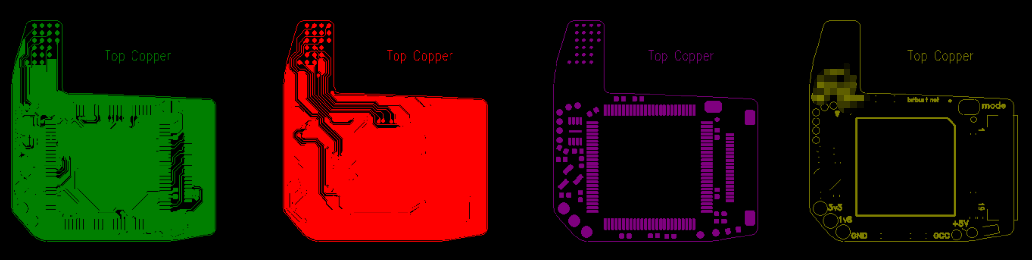
The quotation package should include complete and mutually consistent design data. The manufacturer must be able to identify all conductive layers, coverlay openings, stiffener locations, drill features, outline geometry, surface-finish areas, and special mechanical requirements without relying on interpretation.
Gerber Data
Extended Gerber, commonly referred to as RS-274X, remains widely used for flexible PCB fabrication. A complete Gerber package should normally include:
- All copper layers
- Top and bottom coverlay opening layers
- Board outline or mechanical profile
- Drill drawing and NC drill data
- Stiffener layers or clearly referenced stiffener drawings
- Legend or marking layers, if required
- Paste and assembly-related layers when FPCA is included
Layer names should be clear and consistent. Ambiguous file names such as “layer1,” “mask2,” or “mechanical-final-new” increase the risk of incorrect interpretation. A layer map or fabrication note should be included when the construction is not self-explanatory.
ODB++ and IPC-2581
ODB++ and IPC-2581 can provide a more integrated manufacturing data set because they may include layer structure, apertures, drill information, component data, net connectivity, and other fabrication attributes in a single package.
When ODB++ or IPC-2581 data is supplied, it is still good practice to include a fabrication drawing and a PDF data summary. These documents communicate mechanical, material, quality, and commercial requirements that may not be fully represented in the electronic design database.
For official information about IPC standards, data-exchange formats, and electronics manufacturing requirements, refer to the technical resources published by IPC.
Native CAD Files
Native CAD files may be useful for engineering review, but they should not be treated as the only fabrication data unless the manufacturer has specifically agreed to work from that format. Released manufacturing outputs should remain the contractual reference for production.
The RFQ package should clearly identify the revision level of every released file. Gerber, drill, drawing, BOM, and assembly files should all refer to the same design revision.
3. Fabrication Drawing Requirements
The fabrication drawing is one of the most important documents in an FPC quotation package. It should define requirements that cannot be communicated reliably through Gerber data alone.
A professional flexible PCB fabrication drawing should normally include:
- Finished part dimensions and dimensional tolerances
- Datum references and critical-to-function dimensions
- Layer count and approved stack-up
- Base material, copper type, and dielectric construction
- Finished copper thickness
- Overall finished thickness and local thickness requirements
- Coverlay material, thickness, and opening requirements
- Stiffener material, thickness, adhesive, and location
- Surface finish and selective plating areas
- Controlled-impedance requirements
- Minimum bend radius and identified bend zones
- Static-flex or dynamic-flex classification
- Connector-finger geometry and mating-thickness requirements
- Electrical test and inspection requirements
- Applicable IPC class or customer acceptance criteria
- Panelization, tooling-hole, and delivery-format requirements
Critical Dimensions and Tolerances
Not every dimension requires the same tolerance. The drawing should distinguish between general dimensions and critical dimensions that directly affect fit, connector engagement, component alignment, enclosure assembly, or mechanical motion.
Critical features may include connector-finger width, exposed contact length, stiffener thickness, distance between mounting holes, local finished thickness, outline-to-pad position, and the location of bend or fold lines.
Unnecessarily tight tolerances can increase manufacturing cost and reduce yield. Tolerances should therefore reflect the actual functional requirement rather than a default drawing template.
Revision and Change Control
The fabrication drawing should display a clear part number, revision identifier, issue date, and change history. If the design changes after quotation, the updated package should identify whether the change affects materials, stack-up, tooling, panelization, test requirements, or assembly scope.
Engineering changes introduced after tooling release may create additional non-recurring engineering charges, replacement tooling, revised test fixtures, or lead-time changes. Clear revision control protects both the buyer and the manufacturer from producing against obsolete data.
4. FPC Stack-Up and Material Specifications
The FPC stack-up is a primary quotation input because it determines material selection, finished thickness, flexibility, impedance behavior, lamination process, drilling method, and overall manufacturing complexity. A quotation based only on layer count is not sufficient for a technically controlled project.
The RFQ should identify whether the required construction is single-sided, double-sided, multilayer flexible, or rigid-flex. It should also distinguish between adhesive-based and adhesiveless laminate systems where this affects flex performance, thickness, thermal reliability, or cost.
Base Dielectric Material
Polyimide is the most common dielectric material used in flexible circuits because of its thermal resistance, dimensional stability, dielectric performance, and flexibility. The RFQ should specify the required dielectric thickness or provide an approved stack-up drawing.
If a specific material brand, material family, flame rating, halogen-free requirement, or regulatory condition applies, it should be stated clearly. When no approved material is specified, the manufacturer may quote an equivalent production-grade laminate that meets the stated electrical and mechanical requirements.
Adhesive-Based and Adhesiveless Laminate
Adhesive-based laminates use a bonding layer between the copper and polyimide film. They can be suitable for many static-flex and cost-sensitive applications, but the additional adhesive contributes to total thickness and may reduce thermal and dimensional performance.
Adhesiveless laminates eliminate the separate bonding adhesive between copper and polyimide. They are commonly selected for fine-line circuits, thin constructions, controlled-impedance designs, multilayer FPCs, and applications requiring improved flex endurance.
If the design requires dynamic flexing, reduced thickness, tighter dimensional control, or repeated thermal cycling, the material construction should be confirmed before quotation rather than left as a general supplier choice.
Static Flex and Dynamic Flex Classification
The RFQ should state whether the circuit will be bent only during installation or repeatedly flexed during operation.
- Static flex: The circuit is bent during installation and remains in a substantially fixed position during service.
- Dynamic flex: The circuit is repeatedly bent, rolled, or moved during product operation.
Dynamic-flex requirements can affect copper type, stack-up symmetry, bend radius, coverlay construction, plating limits, trace orientation, and inspection criteria. The expected flex-cycle requirement should be provided whenever available.
5. Copper Thickness and Finished Thickness
Copper specification must be stated precisely because base copper thickness, plated copper, and finished copper thickness are not always the same. These values affect current capacity, trace geometry, etching tolerance, flex performance, via reliability, and total circuit thickness.
Base Copper and Finished Copper
The RFQ should identify the intended copper thickness by layer. Common flexible-circuit base copper thicknesses include approximately 12 µm, 18 µm, and 35 µm, although other values may be available.
Where plated through-holes or vias are present, the finished copper thickness may be greater than the starting copper thickness because of panel plating or pattern plating. The drawing should clarify whether the stated value refers to base copper, nominal copper, or finished copper.
Rolled Annealed and Electrodeposited Copper
The copper type should be specified when flex endurance is important.
- Rolled annealed copper: Commonly preferred for dynamic-flex and repeated-bending applications because of its grain structure and improved fatigue resistance.
- Electrodeposited copper: Commonly used in static-flex and general-purpose applications where repeated motion is limited.
If the application requires repeated flexing but the copper type is not stated, the quotation may be technically incomplete or based on a construction that does not meet the final reliability target.
Overall Finished Thickness
Overall finished thickness should be stated where it affects connector fit, enclosure clearance, folding behavior, mechanical routing, or assembly tooling. In flexible circuits, local thickness can vary because of coverlay, adhesive, copper plating, stiffeners, shielding films, and surface-finish buildup.
For connector interfaces, the required mating thickness should be specified separately from the general FPC thickness. The manufacturer should not be expected to infer connector-fit requirements from the circuit drawing alone.
Tight finished-thickness tolerances may require material selection, controlled lamination, dedicated measurement methods, and additional process control. These requirements can affect both pricing and lead time.
6. Coverlay Requirements
Polyimide coverlay protects the copper circuitry and provides electrical insulation, environmental protection, and mechanical support. Coverlay requirements should be defined separately from conventional rigid-PCB solder mask because the materials, processing methods, tolerances, and flex behavior are different.
Coverlay Material and Thickness
The RFQ should identify the coverlay material, polyimide thickness, adhesive thickness, and finished construction where these values are functionally important. Thicker coverlay can improve dielectric protection but may increase local stiffness and reduce flexibility.
Coverlay Openings
Coverlay opening data should clearly identify exposed solder pads, connector fingers, test points, bonding areas, and other unprotected copper features. Fine-pitch openings should be reviewed against the manufacturer’s punching, routing, or laser-cutting capability.
The quotation should also account for registration tolerance, adhesive squeeze-out, minimum coverlay web width, and coverlay overlap around conductor edges. Openings that are too tight can partially cover pads, while excessive openings can reduce pad support and expose unnecessary copper.
Photoimageable Covercoat
Some designs may use a flexible photoimageable covercoat instead of conventional laminated polyimide coverlay. This option can support finer openings and more complex pad geometry, but it should be specified explicitly because it differs in processing, flexibility, thickness, and long-term mechanical behavior.
The manufacturer should not substitute photoimageable covercoat for polyimide coverlay, or vice versa, without approval when the material system is critical to product reliability.
7. Stiffener Material, Thickness, and Location
Stiffeners provide local reinforcement under connectors, components, solder joints, mounting areas, and contact interfaces. Because stiffeners affect local thickness, assembly support, connector fit, bend behavior, and adhesive processing, they must be fully defined in the RFQ package.
Common Stiffener Materials
- Polyimide stiffener: Used where moderate reinforcement and a thin profile are required.
- FR-4 stiffener: Commonly used under connectors and component areas that require greater rigidity.
- Stainless steel stiffener: Used where high dimensional stability, wear resistance, strength, or precise local thickness is required.
The RFQ should state the stiffener material, finished thickness, adhesive type where controlled, dimensional tolerance, and exact location. A simple note such as “add stiffener” is not sufficient for accurate engineering review or quotation.
Connector Interface Thickness
For zero insertion force, low insertion force, board-to-board, or other connector interfaces, the required total mating thickness should be defined. This value normally includes the FPC, adhesive, and stiffener construction.
The connector manufacturer’s specification should be treated as the primary reference. Incorrect mating thickness can result in poor insertion, low contact force, intermittent electrical performance, or mechanical damage.
Stiffener Edge and Bend-Zone Relationship
The position of the stiffener edge relative to the bend area should be shown clearly. An abrupt stiffness transition can concentrate mechanical strain and increase the risk of copper fatigue, coverlay cracking, or delamination.
When a stiffener supports a connector or component area, the drawing should identify whether the adjacent flex section is static or dynamic and whether a minimum clearance or strain-relief geometry is required.
8. Surface Finish and Contact Areas
Surface finish affects solderability, contact resistance, storage life, assembly compatibility, wire bonding, connector wear, and long-term reliability. The RFQ should identify the required finish and the exact areas where it applies.
Common Surface Finishes
- ENIG: Commonly used for solderable pads, fine-pitch assembly, and general-purpose flexible circuits.
- Immersion tin: Used where a flat solderable surface is required and the application is compatible with the process and storage conditions.
- OSP: A cost-effective finish for selected soldering applications, although handling and storage conditions must be controlled.
- Hard gold: Used on connector fingers and repeated-contact areas where wear resistance and stable contact performance are required.
The RFQ should state whether the finish applies to all exposed copper or only to selected regions. Mixed finishes, selective plating, nickel thickness, hard-gold thickness, or special contact requirements should be identified clearly on the fabrication drawing.
Connector Fingers and Contact Areas
Connector-finger requirements should include contact pitch, exposed length, contact width, surface finish, edge profile, mating thickness, and any bevel or chamfer requirement. For repeated insertion cycles, the contact finish should be compatible with the connector manufacturer’s specification.
If a hard-gold contact area is required, the RFQ should define the plating thickness and whether a nickel underlayer is specified. The manufacturer should not infer connector-contact requirements from appearance alone.
9. Bend Radius and Flex Classification
Bend requirements are a critical part of FPC RFQ requirements because they affect laminate selection, copper type, stack-up, coverlay construction, stiffener placement, and finished thickness. The quotation package should identify both the intended bend geometry and the expected operating condition.
Minimum Bend Radius
The RFQ should define the minimum bend radius where it is functionally controlled. A simple note such as “flexible area” is not sufficient when the circuit must fold into a compact enclosure or move during operation.
The acceptable bend radius depends on total thickness, layer count, copper thickness, copper type, plating, coverlay construction, and whether the circuit is static or dynamic. The final value should be reviewed against the actual proposed stack-up.
Bend Direction and Bend Zone
The fabrication or mechanical drawing should indicate the bend direction, bend line, and active bend zone. This information helps the manufacturer evaluate trace orientation, via location, copper balance, stiffener clearance, and local stress concentration.
Vias, plated through-holes, solder joints, component pads, and abrupt stiffener edges should generally be kept outside dynamic bend regions. If these features cannot be relocated, the exception should be reviewed during DFM.
Expected Flex Cycles
For dynamic-flex applications, the RFQ should state the expected number of flex cycles, operating speed, bend radius, travel length, environmental temperature, and any torsional movement. These conditions can significantly affect material selection and reliability expectations.
Without an expected flex-life requirement, the manufacturer can only evaluate general manufacturability and cannot confirm suitability for a specific dynamic-motion profile.
10. Controlled Impedance Requirements
Controlled impedance should be specified whenever signal integrity depends on a defined transmission-line structure. High-speed interfaces, differential pairs, RF signals, and timing-sensitive interconnects may require impedance control even in compact flexible circuits.
Required Impedance Information
The RFQ should provide:
- Target impedance value
- Single-ended or differential configuration
- Permitted tolerance
- Reference layer
- Controlled trace locations or net names
- Preferred test method
- Whether an impedance coupon is required
The proposed trace width and spacing should be treated as design inputs rather than fixed production values unless they have already been validated against the final manufacturing stack-up. The manufacturer may need to adjust conductor geometry to achieve the required impedance after considering finished copper thickness, dielectric thickness, dielectric constant, and etching tolerance.
Reference Planes and Hatching
Solid reference planes provide stable return paths but can increase stiffness. Hatched ground planes are sometimes used in flex regions to reduce mechanical rigidity, but the hatch geometry must still support the required impedance and electromagnetic compatibility performance.
If a hatched plane is used, the RFQ should not assume that rigid-PCB impedance rules apply directly. The final construction should be reviewed with the manufacturer and, where necessary, verified through impedance modeling and testing.
11. Electrical Testing and Quality Requirements
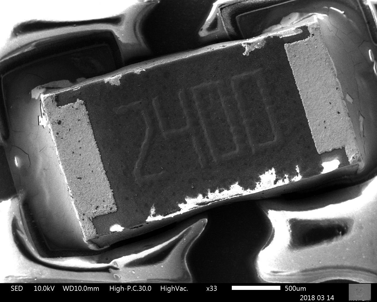
Electrical testing and acceptance criteria should be defined before quotation because test coverage, fixture design, inspection level, documentation, and traceability can affect both cost and lead time.
Continuity and Isolation Testing
For most FPC projects, 100% electrical testing should verify continuity and isolation against the released netlist. The RFQ should identify whether flying-probe testing, dedicated fixture testing, or another method is required.
Prototype quantities are often tested using flying-probe equipment, while higher-volume production may justify a dedicated electrical test fixture. Fixture cost should normally be treated as a non-recurring engineering or tooling charge.
IPC Class and Acceptance Criteria
If the product must comply with a specific IPC class, customer standard, medical requirement, automotive requirement, aerospace requirement, or internal quality specification, this should be stated in the RFQ.
The buyer should identify whether the required acceptance level is based on IPC-6013, IPC-A-600, IPC-A-610 for assembly, or another applicable document. The exact revision and class should be stated where contractually important.
Inspection and Documentation
Additional quality deliverables may include:
- First article inspection report
- Certificate of conformance
- Material certificate
- Microsection report
- Impedance test report
- Dimensional inspection report
- Solderability report
- Ionic contamination test
- RoHS or REACH declaration
- Lot traceability records
These requirements should be included at the RFQ stage. Requesting additional reports after production has started may not be possible without extra cost, sample consumption, or lead-time impact.
12. Quantity and Commercial Requirements
Accurate quotation also depends on clear commercial information. The same FPC design can have significantly different unit pricing depending on prototype quantity, production volume, panel utilization, material availability, tooling strategy, test method, and delivery schedule.
Prototype, Pilot-Run, and Volume Quantity
The RFQ should distinguish between prototype, engineering validation, pilot-run, and volume-production quantities. A request for “100 pieces” may not provide enough context if the project is expected to scale to several thousand units per month.
Where available, provide:
- Initial prototype quantity
- Pilot-run quantity
- Expected monthly or annual usage
- Estimated project lifetime
- Target ramp-up schedule
- Preferred shipment frequency
Forecast information allows the manufacturer to evaluate whether prototype tooling, production tooling, dedicated electrical test fixtures, material reservations, or price-break structures are appropriate.
Price Breaks and Annual Demand
For procurement planning, the RFQ may request pricing at multiple quantity levels. Typical price-break requests can include prototype, low-volume, medium-volume, and forecasted production quantities.
The manufacturer should be informed whether the requested volume is firm demand, an estimated annual usage, or a planning forecast. This distinction affects material planning, capacity allocation, and commercial validity.
Currency, Trade Terms, and Shipping Destination
The RFQ should state the required quotation currency, delivery destination, and preferred Incoterm where applicable. Freight, customs clearance, import duties, insurance, and local taxes may not be included unless specifically requested.
For international projects, the buyer should also clarify whether shipment will be arranged through the manufacturer’s logistics account, the buyer’s nominated forwarder, or a customer courier account.
13. Panelization and Delivery Format
Panelization affects fabrication yield, handling stability, assembly efficiency, electrical testing, depanelization, packaging, and final unit cost. The RFQ should state whether the customer requires individual pieces, production panels, assembly arrays, or a supplier-proposed panel format.
Customer-Defined and Supplier-Defined Panels
If the customer provides a panel drawing, the quotation should follow the specified array size, tooling-hole pattern, fiducials, breakaway features, and routing method.
If no panel is defined, the manufacturer may propose a production panel optimized for material utilization and process capability. The buyer should indicate whether approval is required before tooling release.
Assembly Panel Requirements
For FPCA projects, panel design should support solder paste printing, component placement, reflow, inspection, handling, and depanelization. Flexible circuits may require temporary carriers, support frames, pressure-sensitive adhesive, or dedicated fixtures during assembly.
The RFQ should identify any required:
- Panel outline dimensions
- Unit array and orientation
- Global and local fiducials
- Tooling holes
- Breakaway tabs or routing bridges
- Temporary support carriers
- Depanelization method
- Packaging orientation
Individual Piece Delivery
If individual pieces are required, the RFQ should state whether parts must be delivered flat, folded, pre-formed, interleaved, tray-packed, bagged, or supplied with protective liners.
Handling and packaging requirements are particularly important for thin flexible circuits, exposed connector fingers, assembled components, and circuits with pre-applied adhesive or release liners.
14. Lead Time, Tooling, and Non-Recurring Engineering Charges
Lead time should be evaluated against the actual technical scope. Prototype urgency, material availability, special finishes, controlled impedance, dedicated test fixtures, assembly complexity, and customer approval cycles can all affect delivery.
Target Lead Time
The RFQ should state the requested shipment date or target lead time. It should also clarify whether the schedule applies from RFQ receipt, purchase order receipt, engineering approval, material availability, or tooling release.
A quoted production lead time normally begins only after all technical questions are closed, the final data package is approved, commercial terms are confirmed, and any required tooling has been released.
Tooling and NRE Items
Non-recurring engineering and tooling charges may include:
- Phototooling or laser direct imaging setup
- Outline or coverlay tooling
- Stiffener tooling
- Dedicated electrical test fixtures
- Assembly pallets or support carriers
- Solder paste stencils
- Programming fixtures
- Special inspection gauges
- Engineering review and process development
The quotation should identify which charges are one-time, reusable, revision-specific, or subject to replacement after an engineering change. Tool ownership and storage period should also be clarified where contractually important.
Expedited Production
Expedited service may be available for selected designs, but it should not be assumed. Material procurement, lamination cycles, drilling, plating, coverlay processing, stiffener bonding, testing, and final inspection all impose practical process limits.
An urgent RFQ should identify the latest acceptable shipment date and whether partial shipment is permitted. This allows the manufacturer to evaluate realistic acceleration options without compromising quality.
15. FPCA Quotation Files and Assembly Scope
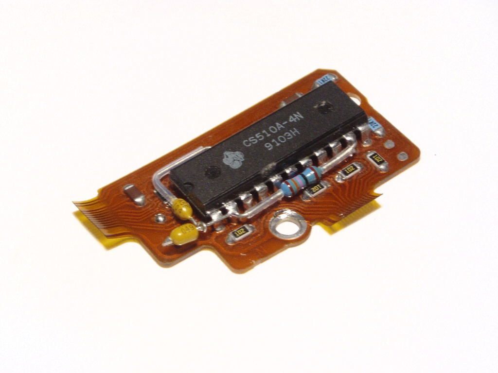
If flexible PCB assembly is included, the RFQ must define both the bare FPC requirements and the assembly scope. A fabrication-only data package is not sufficient for accurate FPCA quotation.
Bill of Materials
The bill of materials should include the reference designator, manufacturer name, manufacturer part number, description, package, quantity per assembly, approved alternatives, and sourcing responsibility.
Where possible, the BOM should identify:
- Do-not-substitute components
- Approved alternate part numbers
- Customer-supplied components
- Supplier-sourced components
- Long-lead or allocation-risk items
- Moisture-sensitive devices
- Programmed or serialized devices
Component Placement List
The component placement list, also referred to as CPL, centroid, pick-and-place, or XY data, should include reference designators, X and Y coordinates, rotation, side, and package information.
The coordinate origin and rotation convention should be consistent with the assembly drawing and released CAD data. Ambiguous rotation or mirrored bottom-side data can create placement errors.
Assembly Drawing and Special Instructions
The assembly drawing should show component locations, polarity, orientation, connector direction, mechanical restrictions, adhesive areas, heat-sensitive regions, inspection points, and any post-assembly forming requirements.
Special instructions should identify requirements such as:
- Lead-free or leaded soldering process
- Selective soldering or hand soldering
- Low-temperature solder alloy
- Underfill or staking adhesive
- Conformal coating
- Connector reinforcement
- Component height restrictions
- Cleaning requirements
- Functional testing
- Programming and serialization
Component Procurement Responsibility
The RFQ should state whether the project is turnkey, consigned, or partially consigned.
- Turnkey: The assembly supplier procures all components and materials.
- Consigned: The customer supplies all components.
- Partial consignment: Procurement responsibility is divided between the customer and supplier.
For consigned components, the buyer should provide expected delivery date, packaging condition, quantity allowance, date-code requirements, and traceability information. Additional quantity may be required for feeder setup, process validation, inspection, and normal attrition.
16. Common FPC RFQ Information Gaps
Many quotation delays are caused not by complex circuit design, but by missing or inconsistent information. The following issues are commonly identified during FPC engineering review.
Missing Stack-Up Information
A request that specifies only “2-layer FPC” does not define the dielectric thickness, copper type, finished copper, coverlay, adhesive system, or total thickness. These parameters must be confirmed before the manufacturer can evaluate bend performance, impedance, and final cost.
Unclear Stiffener Requirements
Notes such as “add reinforcement” or “add backing” are not sufficient. The RFQ should define stiffener material, thickness, location, adhesive, dimensional tolerance, and the required total connector-interface thickness.
No Bend or Flex-Life Information
A flexible circuit may be intended for one-time installation, occasional service movement, or continuous dynamic flexing. Without this information, the manufacturer cannot properly evaluate copper type, bend radius, stack-up, or expected service life.
Inconsistent Revisions
Gerber, drill, fabrication drawing, BOM, CPL, and assembly files must all refer to the same revision. Mixed revisions create a serious risk of incorrect quotation, incorrect tooling, or production against obsolete data.
Undefined Surface Finish
The finish should not be left as a general supplier assumption when the design includes solderable pads, connector fingers, repeated-contact areas, wire bonding, or selective plating.
Missing Quantity and Forecast
Prototype quantity alone may not be enough for commercial evaluation. Expected pilot-run quantity, annual usage, target ramp-up, and delivery frequency help the manufacturer select the correct tooling, material-planning, and price-break strategy.
Incomplete FPCA Data
For assembly quotation, missing BOM part numbers, incomplete placement data, unclear sourcing responsibility, or absent assembly drawings can prevent accurate component pricing and process evaluation.
17. FPC RFQ Checklist
Before submitting a quotation request, the buyer should confirm that the package includes the following information.
Design and Fabrication Files
- Gerber, ODB++, or IPC-2581 data
- NC drill files
- Fabrication drawing
- Layer map and revision identification
- Board outline and dimensional tolerances
- Stiffener and coverlay data
Material and Construction Requirements
- Layer count and approved stack-up
- Polyimide dielectric thickness
- Adhesive-based or adhesiveless construction
- Rolled annealed or electrodeposited copper
- Base copper and finished copper thickness
- Overall finished thickness
- Coverlay material and thickness
- Stiffener material, thickness, and location
- Surface finish and selective-plating requirements
Mechanical and Reliability Requirements
- Static-flex or dynamic-flex classification
- Minimum bend radius
- Bend direction and bend zone
- Expected flex cycles
- Connector mating thickness
- Critical dimensions and tolerances
- Operating environment and temperature range, where relevant
Electrical and Quality Requirements
- Controlled-impedance values and tolerances
- Reference layers and controlled nets
- 100% continuity and isolation testing
- Applicable IPC class or customer standard
- First article, dimensional, impedance, or microsection reports
- RoHS, REACH, traceability, and certificate requirements
Commercial and Delivery Requirements
- Prototype and production quantities
- Annual usage or forecast
- Target lead time or shipment date
- Required price-break quantities
- Currency and Incoterm
- Shipping destination
- Panel or individual-piece delivery format
- Packaging and labeling requirements
FPCA Requirements
- Complete BOM with manufacturer part numbers
- CPL or pick-and-place data
- Assembly drawing
- Paste data and stencil requirements
- Turnkey, consigned, or partial-consignment scope
- Approved substitutions
- Programming, functional test, and inspection requirements
- Conformal coating, underfill, or special assembly instructions
A complete package allows the manufacturer to provide a quotation that is technically aligned with the final product requirement rather than based on provisional assumptions.
Conclusion
Accurate flexible PCB quotation depends on complete and consistent technical information. Gerber data alone is not enough when the project includes controlled thickness, dynamic flexing, local stiffeners, connector contacts, controlled impedance, special testing, or assembly requirements.
The most effective FPC RFQ requirements combine released design files, a detailed fabrication drawing, material and stack-up specifications, mechanical conditions, quality criteria, quantity forecasts, and delivery expectations. This information allows the manufacturer to evaluate manufacturability, identify technical risk, define tooling, and prepare realistic pricing and lead time.
Before submitting an RFQ, ensure that all files use the same revision and that any assumptions requiring manufacturer confirmation are clearly identified. Early engineering review reduces quotation delays, prevents avoidable redesign, and supports a smoother transition from prototype to volume production.
For additional technical background, review our FPC Design Guidelines, What Is FPC Manufacturing?, and Flexible PCB vs Rigid PCB guides.
You can also review our Flexible PCB Manufacturing and Flexible PCB Assembly / FPCA service capabilities.
To request a quotation, send your released fabrication data, drawing, quantity, target lead time, and assembly files where applicable. FPCFAB can review the package and provide engineering feedback before quotation.