FPC Manufacturing refers to the fabrication process used to produce flexible printed circuits, also known as flexible PCBs or flexible printed circuit boards. These circuits are designed with thin, bendable materials so they can fit into compact electronic products, replace traditional wiring, and support reliable electrical connection in space-constrained assemblies.
Unlike standard rigid PCBs, an FPC is built on a flexible dielectric substrate, typically polyimide, combined with copper conductors, coverlay, adhesive systems, stiffeners, and suitable surface finishes. Because the circuit can bend or fold, the manufacturing process must consider not only electrical performance, but also mechanical reliability, bending radius, stack-up balance, material thickness, and final assembly conditions.
For engineers, procurement teams, and product developers, understanding FPC manufacturing helps reduce design risk, improve quotation accuracy, and prepare better files for prototype or production builds.
What Is an FPC?
An FPC, or flexible printed circuit, is a printed circuit structure made with flexible insulating materials and patterned copper conductors. It is commonly used when a product requires lightweight wiring, compact routing, repeated bending, or connection between moving or space-limited parts.
FPCs are widely used in battery packs, sensors, display modules, medical devices, automotive electronics, wearable devices, industrial equipment, cameras, connectors, and compact consumer electronics.
Compared with discrete wire harnesses, a flexible printed circuit can provide a thinner profile, more stable routing, improved assembly repeatability, and better integration with connectors, components, stiffeners, and mechanical structures.
Common Types of Flexible Printed Circuits
FPC manufacturing can support different circuit structures depending on the application, circuit density, bending requirement, and assembly method.
- Single-sided FPC: one copper layer on a flexible substrate, suitable for simple routing and low-complexity interconnects.
- Double-sided FPC: copper on both sides with vias for interconnection, used when more routing density is required.
- Multilayer FPC: multiple copper layers laminated together for more complex electrical designs.
- FPC with stiffener: flexible circuits combined with FR4, PI, stainless steel, or aluminum stiffeners to support connectors, components, or assembly areas.
- FPC with adhesive backing: flexible circuits with pressure-sensitive adhesive for mounting or positioning inside the final product.
- Rigid-flex PCB: a hybrid structure combining rigid board sections and flexible interconnection areas in one integrated design.
Key Materials Used in FPC Manufacturing
Material selection is one of the most important parts of flexible PCB manufacturing. It affects bending performance, thermal resistance, dimensional stability, soldering reliability, thickness control, and long-term product performance.
- Polyimide substrate: the most common flexible base material used for its heat resistance and mechanical flexibility.
- Copper foil: commonly rolled annealed copper or electrolytic copper, selected based on bending and electrical requirements.
- Coverlay: a protective insulating layer used instead of traditional solder mask in many flexible circuit designs.
- Adhesive layer: used in many FPC stack-ups to bond copper, coverlay, and other layers.
- Stiffener: added to selected areas to support connectors, component mounting, handling, or final assembly.
- Surface finish: such as ENIG, OSP, immersion tin, or other finishes selected according to soldering and contact requirements.
How the FPC Manufacturing Process Works
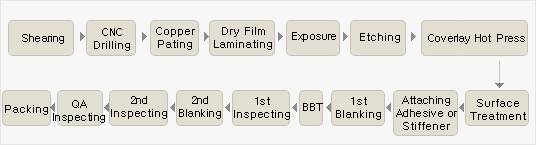
The exact FPC manufacturing flow depends on the stack-up, layer count, copper thickness, surface finish, and product structure. However, most flexible printed circuit projects follow a similar engineering and fabrication sequence.
1. File Review and DFM Check
Before production, the manufacturer reviews Gerber files, drill files, stack-up information, material requirements, line width, spacing, via design, bending area, stiffener position, and surface finish. This DFM review helps identify potential risks before the project enters fabrication.
2. Material Preparation
Flexible base materials, copper foil, coverlay, adhesive films, and stiffener materials are selected according to the design requirements. For projects with bending or folding requirements, material thickness and copper type are especially important.
3. Circuit Pattern Formation
The copper pattern is formed through imaging, exposure, developing, and etching. This step defines the electrical traces, pads, and connection areas of the flexible circuit.
4. Drilling and Via Formation
For double-sided or multilayer FPCs, drilling and via formation are required to connect different copper layers. Hole size, registration, and plating quality are important for electrical reliability.
5. Coverlay Lamination
Coverlay is laminated onto the flexible circuit to protect the copper traces while leaving pads, connector areas, or soldering locations exposed. Accurate coverlay opening is important for assembly and soldering.
6. Surface Finish
The exposed copper pads receive a suitable surface finish, such as ENIG, OSP, or immersion tin. The choice depends on solderability, connector requirements, storage conditions, and final product application.
7. Stiffener Bonding
If the design includes stiffeners, they are bonded to specific areas to improve mechanical support. Stiffeners are commonly used under connectors, soldering areas, component areas, or assembly handling zones.
8. Electrical Testing and Final Inspection
After fabrication, the flexible PCB is inspected and electrically tested to confirm circuit continuity and detect opens or shorts. Dimensional inspection, visual inspection, and packaging checks may also be performed before shipment.
Design Factors That Affect FPC Manufacturing
A successful flexible PCB project depends on early design decisions. Even a technically correct circuit may be difficult to manufacture or assemble if bending areas, material thickness, connector positions, and stiffener locations are not considered properly.
- Bending radius: the bend area should be designed according to material thickness, copper structure, and product movement.
- Copper thickness: thicker copper may improve current capacity but can reduce flexibility.
- Trace direction: trace routing in the bend area should avoid unnecessary stress concentration.
- Pad and connector area: connector pads often need stiffener support to improve insertion and assembly reliability.
- Stack-up balance: an unsuitable stack-up may increase warpage, stress, or manufacturing difficulty.
- Assembly process: SMT, connector soldering, hand soldering, and fixture requirements should be considered before production.
FPC Manufacturing vs. Flexible PCB Assembly
FPC manufacturing usually refers to the fabrication of the bare flexible printed circuit. Flexible PCB assembly, also called FPC assembly or FPCA, refers to mounting components, soldering connectors, bonding stiffeners, and turning the bare FPC into a functional electronic assembly.
In many projects, the bare FPC design and the FPCA process must be reviewed together. For example, connector location, component layout, stiffener position, soldering area, and fixture design may affect both FPC fabrication and assembly yield.
For this reason, customers often benefit from early communication between the design team, bare board manufacturer, and assembly supplier.
Files Needed for an FPC Manufacturing Quote
To prepare an accurate FPC manufacturing quotation, customers should provide as much technical information as possible. Complete files help reduce back-and-forth communication and allow the manufacturer to evaluate cost, lead time, and feasibility more accurately.
- Gerber files
- Drill files
- Stack-up drawing or material requirements
- Board thickness and copper thickness requirements
- Surface finish requirement
- Stiffener material and location if required
- Quantity and target lead time
- BOM and assembly drawing if FPCA service is also needed
- Application or reliability requirements if available
When Should You Use an FPC?
Flexible printed circuits are often selected when a rigid PCB or wire harness cannot meet the product structure, space, weight, or assembly requirements.
- When the product requires bending or folding
- When the available space is limited
- When lightweight interconnection is important
- When consistent routing is needed for batch assembly
- When connectors, sensors, LEDs, or modules must be integrated into a compact structure
- When wire harness assembly becomes too complex or unstable
How FPCFAB Supports Flexible PCB Projects
FPCFAB supports custom FPC manufacturing and flexible PCB assembly projects for customers who need practical engineering communication, manufacturability review, and production coordination.
We can review Gerber files, stack-up requirements, material selections, stiffener locations, surface finish requirements, BOM details, and assembly drawings before quotation. This helps customers identify potential manufacturing or assembly risks early in the project.
For FPC manufacturing service details, visit our Flexible PCB Manufacturing page. For component mounting, connector soldering, stiffener bonding, and full FPCA support, visit our Flexible PCB Assembly / FPCA page.
Conclusion
FPC manufacturing is not only about producing a thin flexible circuit. It requires careful coordination between material selection, stack-up design, bending performance, copper patterning, coverlay, stiffeners, surface finish, and final assembly requirements.
A well-prepared FPC project can reduce production risk, improve assembly stability, and help the final product achieve a more compact and reliable structure.
If you are preparing a flexible PCB prototype, FPC production project, or FPCA assembly requirement, you can send your files and project details through our RFQ page.
For additional engineering guidance, read our FPC Design Guidelines covering bend radius, copper thickness, stack-up design, coverlay, stiffeners, vias, and design-for-manufacturability considerations.
When preparing files for pricing and engineering review, use our FPC RFQ Requirements guide to confirm the required Gerber data, fabrication drawing, stack-up, materials, quantities, testing requirements, lead time, and FPCA documentation.